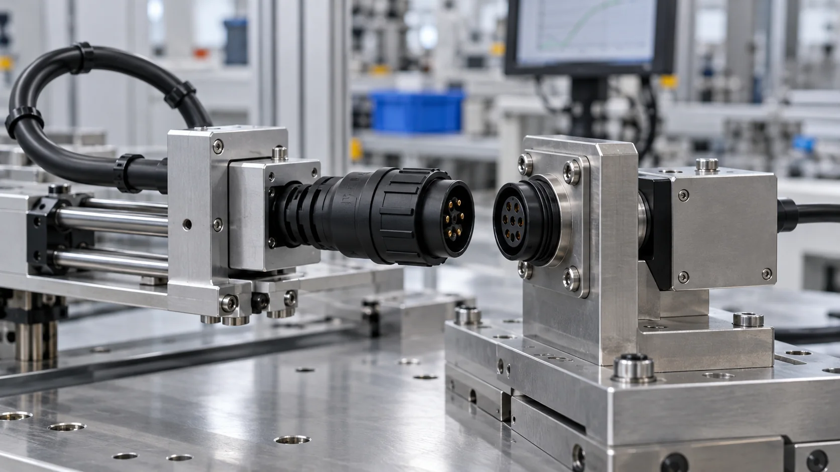
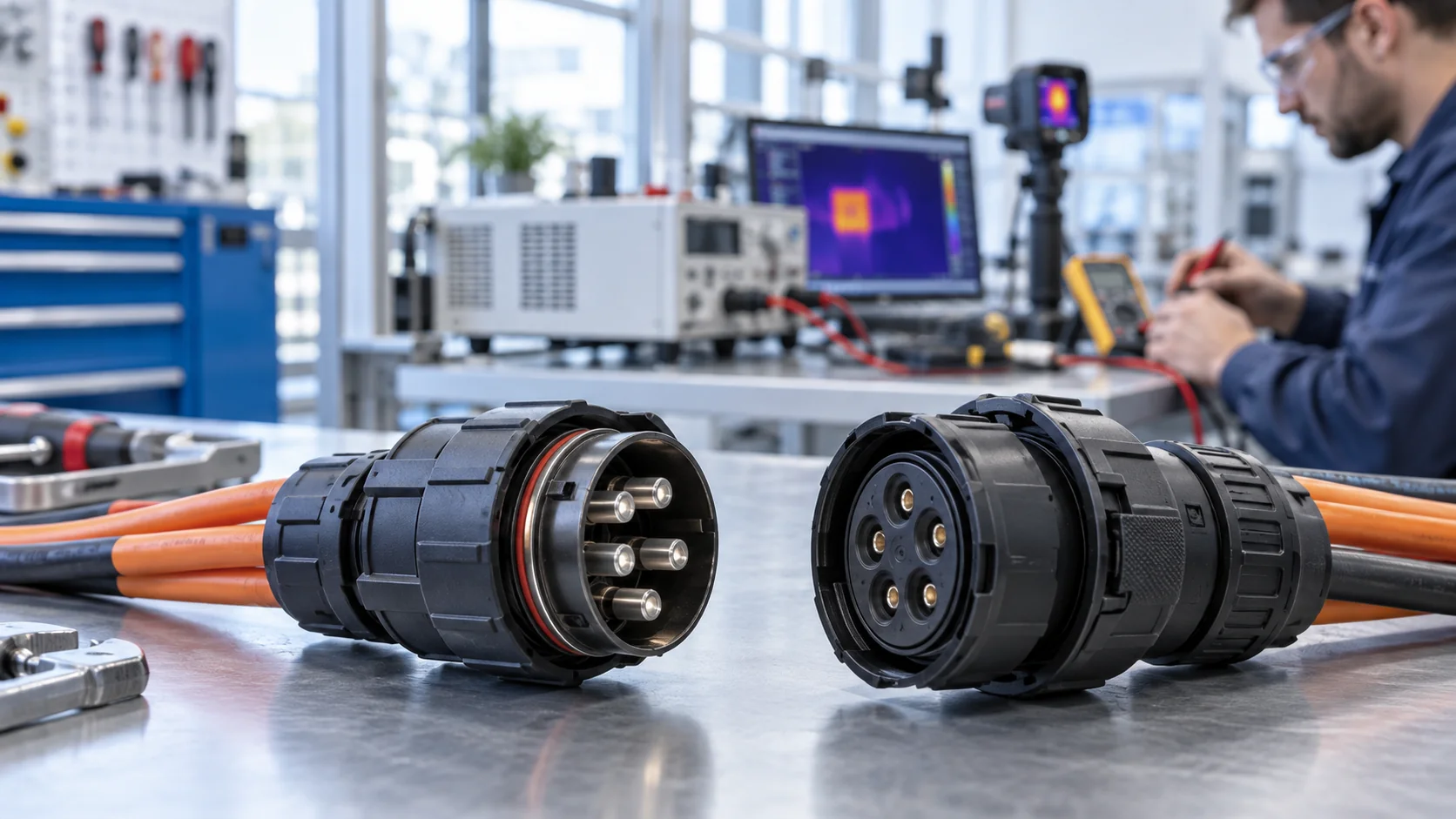
Industrial connectors can pass a stationary continuity check and still lose contact when a machine vibrates. This guide helps OEM engineers turn an intermittent fault into a reviewable test plan: define the installed assembly, reproduce cable support, monitor short interruptions and agree on acceptance criteria before testing. Use it to compare evidence and prepare a technical review, not as a universal vibration rating or proof that a particular connector is qualified.
Start with the Fault, Not a Generic Vibration Rating
A machine that stops only during acceleration presents a different problem from a connector that becomes loose after transport. Begin with a fault record: which circuit fails, what the machine is doing, whether the fault clears without intervention, and whether temperature or cable position changes the result. Preserve controller timestamps and photographs before reseating the connection. Reseating can remove the evidence you need.
Separate three observations. Mechanical movement describes what the housing or cable does. Electrical disturbance describes what the contact path does. Functional failure describes what the connected equipment does. They may occur together, but one observation cannot establish the others. A controller reset could originate in the power supply, software or shielding rather than the connector.
For each suspected event, record the affected assembly revision and the most recent maintenance action. Compare a known-good installation without treating one successful comparison as statistical proof. The immediate output should be a specific question, such as whether a defined cable support arrangement allows interruptions during machine acceleration. For broader interface choices, start with our industrial connector selection guide, then use the workflow below to evaluate the installed connection.
Freeze the Connector and Harness Configuration
A vibration report is useful only when its specimen represents the assembly being purchased. Record both mating part numbers, contact arrangement, termination method, conductor construction, cable outer diameter, backshell, gland, seals and mounting hardware. A family name or photograph is not enough to establish equivalence between test samples and production parts.
For industrial automation connectors, include the controller-side and machine-side interfaces. Document which contacts carry power, discrete signals or communications. If an adapter or extension is fitted, it becomes part of the investigated path. Mark specimen IDs on a separate tag so identification does not alter the locking mechanism or seal.
Use a controlled assembly drawing with revisions. Record the specified installation torque or engagement procedure, the tool used, and any permitted locking aid. Do not add adhesive, a tie wrap or a secondary clamp solely to make a specimen pass unless that feature will also be part of the released installation.
State any differences from production explicitly. Prototype cable jackets, substitute panel thicknesses and hand-built terminations may be appropriate for development, but they limit what the result proves. A configuration discrepancy should remain visible in the report rather than disappear into a broad statement that the connector passed.
Define the Installation and Exposure Envelope
Describe where the connector sits relative to motors, pumps, gearboxes, frame joints and moving cable routes. Installation location matters because the equipment structure changes the vibration transmitted to the interface. A measurement on an enclosure cover is not automatically representative of a connector mounted on a different bracket.
Build the operating envelope from relevant machine evidence and the applicable product specification. Include normal running, starts, stops, speed changes and transport if transport is within scope. Record the orientation and axes, exposure duration, temperature range and whether the assembly is mated, capped or otherwise configured. State whether electrical loading is applied and why.
Distinguish service investigation from qualification. A diagnostic run may explore several support positions to find a fault. Qualification should use a pre-agreed configuration, severity, monitoring method and acceptance rule. Do not quietly convert the most favorable diagnostic run into a qualification result.
When field measurements are unavailable, identify the engineering assumption and its owner. Agree on a representative development test with the responsible laboratory, then review whether it addresses the actual machine risks. A stronger-looking acceleration value alone does not guarantee a more relevant test: frequency content, duration, mounting and specimen response also need consideration.
Choose the Test Method and Document Its Edition
Sinusoidal and broadband random vibration answer different questions and should not be treated as interchangeable labels. A sinusoidal sweep can help investigate frequency-dependent behavior. A random profile represents excitation distributed across a frequency band. The appropriate method and severity depend on the application specification and the purpose of the evaluation.
IEC 60512-6-4:2002 describes a sinusoidal vibration test method for connectors and related components. The official description does not provide a universal pass level for every industrial connector. Separately, IEC 60068-2-64:2026 addresses broadband random vibration. Select the applicable method and edition through the project specification and qualified laboratory.
A purchase requirement should identify the document, edition, specimen configuration, test parameters and acceptance criteria. Writing only “vibration tested” leaves too many decisions unresolved. A report based on a different edition is not automatically unusable, but any differences relevant to the contract need review.
This guide is an OEM planning framework, not the full procedure from either standard. Obtain the applicable standard and use competent test personnel for execution. Do not infer that a JNICON model holds a qualification merely because a test method is discussed here.
Make the Fixture and Cable Supports Representative
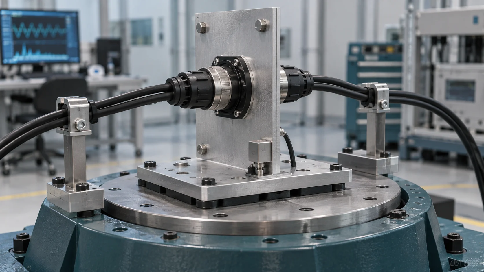
The fixture can change the problem you are trying to measure. Record the mounting plate, bracket geometry, fasteners and the connector position. Ask the laboratory to assess fixture behavior over the intended test range and define appropriate control and response measurement locations. A rigid-looking fixture is not sufficient evidence that the specimen sees the intended excitation.
Cable routing deserves the same attention as the housing. Record unsupported length, bend direction, clamp position and attached mass on both sides. A long unsupported cable can load the termination differently from a short clamped cable. Excessively tight support can conceal a weakness that exists in the machine. Follow the applicable method while documenting how the laboratory arrangement represents the installation.
Photograph the specimen before and after each configuration change. Include a scale or dimensioned drawing in the report, and keep the support details consistent across comparison samples. If a clamp slips during a run, preserve that event as a test deviation instead of simply retightening it and continuing without a record.
The illustration below explains the relationship between the connector, panel and supports. It does not prescribe fixture dimensions, clamp distance or test severity. Those values must come from the agreed plan.
Check Locking, Retention and Assembly Condition
Before vibration, verify complete engagement using the selected model's installation instructions. Threaded, bayonet and push-lock interfaces have different engagement checks. Do not judge a locked condition from general appearance alone, and do not exceed specified torque to compensate for an unexplained fault.
Record baseline photographs of alignment features, coupling position, cable entry and panel attachment. A witness mark may help observe rotation where it does not affect function, but it is only an observation aid. It does not establish contact engagement or prove retention performance. Record any pre-existing damage before exposure.
Separate coupling retention from cable retention. A plug can remain mated while a terminal, gland or cable support moves. Conversely, a sound termination cannot compensate for incomplete mating. Check the applicable mechanical requirements at the correct interface rather than treating the whole assembly as a single pull-test item.
Repeated service disconnection introduces another variable. If prior mating cycles are part of the intended conditioning, define their count and procedure before vibration and retain traceability. Our connector mating-cycle test guide explains how to keep that evidence separate. Passing one test does not automatically qualify the other.
Monitor Contact Disturbance During the Run
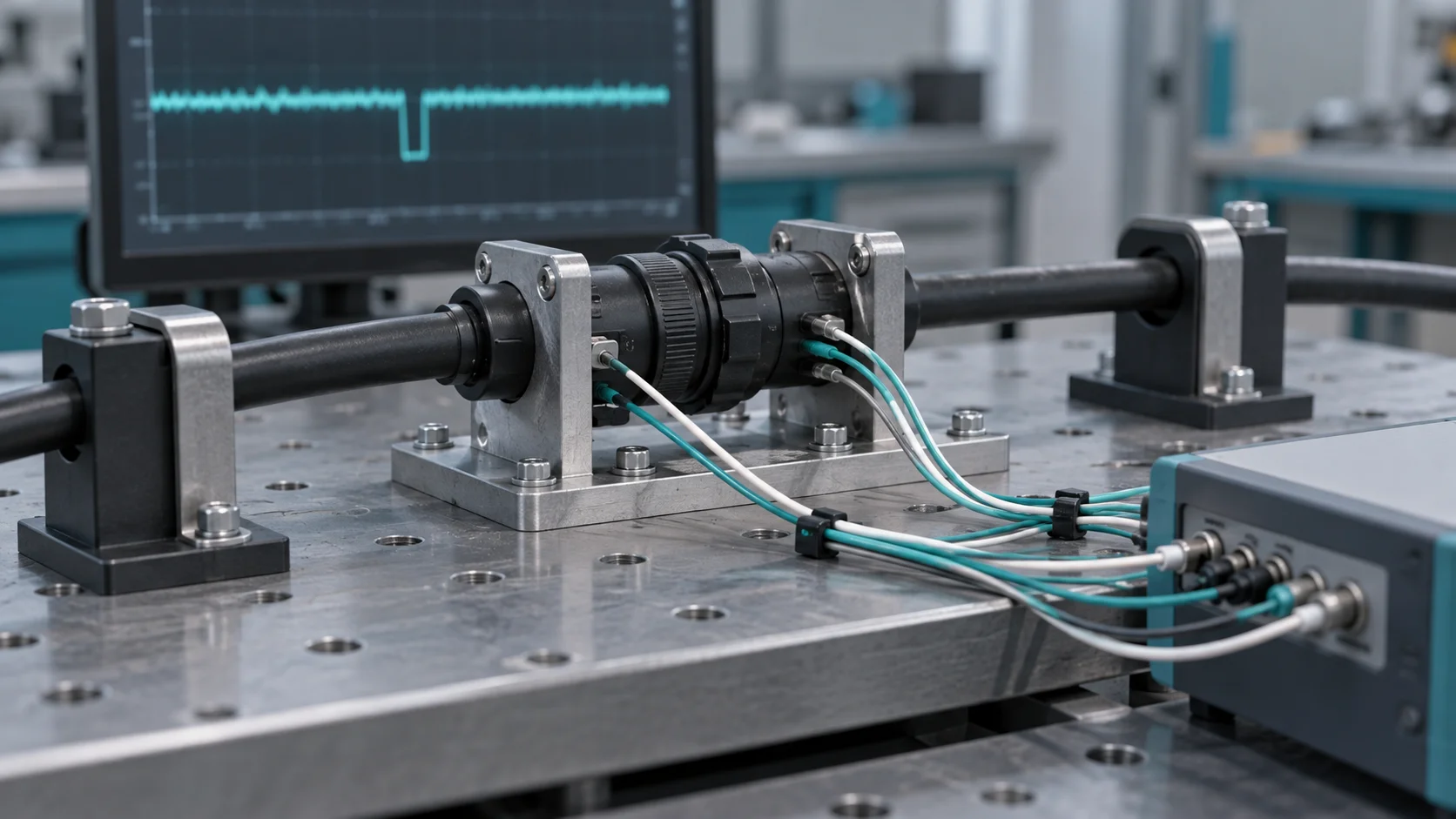
A continuity check taken after a run cannot exclude an interruption that occurred during it. Define what constitutes a disturbance: the monitored circuit, electrical threshold, minimum event duration, monitoring load, timing resolution and recording method. Agree on these settings before comparing samples or accepting a supplier report.
The monitoring system must be capable of detecting the events used in the acceptance rule. A handheld meter display or slowly sampled logger may miss a short interruption. Ask the laboratory to document instrument capability and verify the complete measurement chain, including leads and connectors, with a suitable known event or reference method.
Choose whether contacts are monitored individually or in defined groups. A series path can detect an opening somewhere in that path, but it may not identify the responsible contact. Keep the circuit diagram and channel map with the specimen record. Measurement leads also need support so their own movement does not create a false failure.
When power or communications operation is part of the evaluation, use an approved safe test arrangement and suitable instrumentation. Do not improvise live high-energy connections on a shaker. Record functional behavior separately from electrical disturbance so filtering, retries or buffering do not conceal the event under investigation.
Build an OEM Vibration Test Matrix
Use a matrix to connect every run to a decision. The example below is a planning template, not a standardized severity schedule or a record of completed tests. Enter the actual values agreed by the OEM and laboratory before work starts. Blank acceptance fields mean the plan is not ready for qualification.
| Run group | Configuration to record | Evidence required | Decision |
|---|---|---|---|
| Baseline | Released drawing, specimen IDs, mating state | Initial visual, electrical and functional results | Suitable to begin exposure? |
| Representative installation | Mounting, routing, axes and agreed profile | Excitation record and disturbance event log | Meets the specified requirements? |
| Support comparison | One controlled support change | Comparable response and event records | Does routing influence the fault? |
| Post-test examination | As-tested state before disassembly | Locking, damage and repeat electrical checks | Any unacceptable degradation? |
Keep development comparisons separate from qualification samples. Record sample quantity, selection basis and permitted failures according to the qualification plan. One passing specimen can support an observation, but it cannot establish a population reliability claim without an appropriate sampling rationale.
Give each deviation an owner and disposition. If the shaker stops, a channel drops out or a support is adjusted, record the affected interval and determine whether the run remains valid. Do not combine incomplete segments into an apparently continuous successful exposure without technical review.
Compare Before, During and After Measurements
Use the same defined electrical paths and measurement conditions before and after exposure. Record resistance where relevant, visual condition, locking function and any required insulation or functional checks. The applicable specification determines the limits and whether additional tests are appropriate. Avoid inventing one resistance-change limit for all contact sizes and materials.
Consider the measurement path carefully. Lead resistance and test-point placement can distort a comparison, especially when measuring small changes. Use an appropriate method, stable connections and documented instrument settings. Report both initial and final values with units rather than only a green pass indicator.
Examine the as-tested assembly before disconnecting it. Look for coupling movement, cracked supports, cable-jacket wear, terminal displacement and damage at strain-relief transitions. Photograph findings without claiming that every visible mark caused the electrical failure. If disassembly is needed, record its sequence so evidence is not lost.
A vibration result does not automatically establish sealing, temperature-rise or electromagnetic compatibility performance. Where combined or sequential exposures are required, define the sequence and acceptance checks in advance. For temperature-related problems, use the separate high-current connector overheating checklist and keep its electrical loading conditions distinct from continuity monitoring.
Investigate Failures Without Changing Every Variable
When an event occurs, retain its timestamp, axis, operating condition, channel and the corresponding vibration record. Check whether the monitor, fixture or test leads could explain it before assigning the failure to a connector contact. A repeatable event supports investigation, but repeated testing without a hypothesis can consume samples while obscuring the original fault.
Change one justified variable at a time in development work. Examples include a cable support position, a suspect termination or a mounting bracket. Keep the rest of the configuration and monitoring settings controlled. Document the reason for each comparison and what result would support or weaken the hypothesis.
Contact wear or fretting may be a hypothesis where there is relative motion, but appearance alone is not a complete diagnosis. Preserve damaged parts for appropriate examination and compare them with reference samples. Avoid cleaning, replating or reseating everything before documenting the evidence.
A successful retest after a design change should trigger a controlled drawing or process update, followed by the agreed verification. Do not quietly substitute a corrected sample for a failed one in the report. The final record should explain the original failure, the corrective change, the evidence supporting it and any remaining limits.
Ask Suppliers for Comparable Evidence and Change Control
For an industrial electrical connector, ask for the report scope before comparing headline ratings. Confirm the exact tested mating pair, cable, termination, accessories, mounting, test method and monitoring settings. A result for another pin count or a different backshell may provide context, but it does not automatically cover your assembly.
Request traceable sample identification, test dates, equipment information, configuration photographs, results and deviations. Where confidentiality limits distribution, agree on an appropriate technical review rather than accepting an unsupported marketing statement. Define who approves equivalence between the supplied product and the tested configuration.
Turn the qualification outcome into production controls. Relevant controls may include termination setup, inspection, cable preparation, engagement checks and traceability. Qualification testing and routine production screening serve different purposes; do not assume every production unit should undergo a potentially damaging qualification exposure.
Finally, define change notification. A cable jacket, contact material, plating system, gland or assembly process change can warrant review even when the part number appears unchanged. Specify how the supplier will identify affected lots and which evidence is required before accepting the change. This makes the test useful beyond the first purchase order and reduces ambiguity when an intermittent field fault returns.
Prepare the Drawing Package for a JNICON Review
Send the application context together with the connector request. A useful package includes the mating interface drawing, pin assignment, current and voltage requirements, cable construction, routing, support arrangement and environmental conditions. Include the intended locking method and service-disconnection needs, not just a photograph of the housing.
For a vibration-related concern, attach the fault description, available machine measurements, proposed test specification and acceptance criteria. Identify whether you need a new configuration, a comparison of existing options or support evaluating a failed assembly. Remove customer-confidential details that are unnecessary for the review.
JNICON's product and solution pages below are starting points for discussing connector and cable-assembly configurations. They are not a statement that the listed products have passed the test plan in this article. Confirm model-specific ratings, compatible cable dimensions, installation instructions and available qualification evidence with the technical team.
The most useful review outcome is a bounded decision: a candidate assembly and drawing revision, unresolved requirements, required evidence and the next verification step. Keep commercial questions such as quantity and delivery schedule alongside the technical requirements, so an attractive quotation does not become separated from the configuration that was actually evaluated.
Related Products for an Assembly Review

M16 4Pin Waterproof Connector 10A Screw Locking IP68 for Automation
10A 4 pin screw-locking waterproof circular connector with IP68 rating, field installable or molded with cable for industrial automation and measurement.
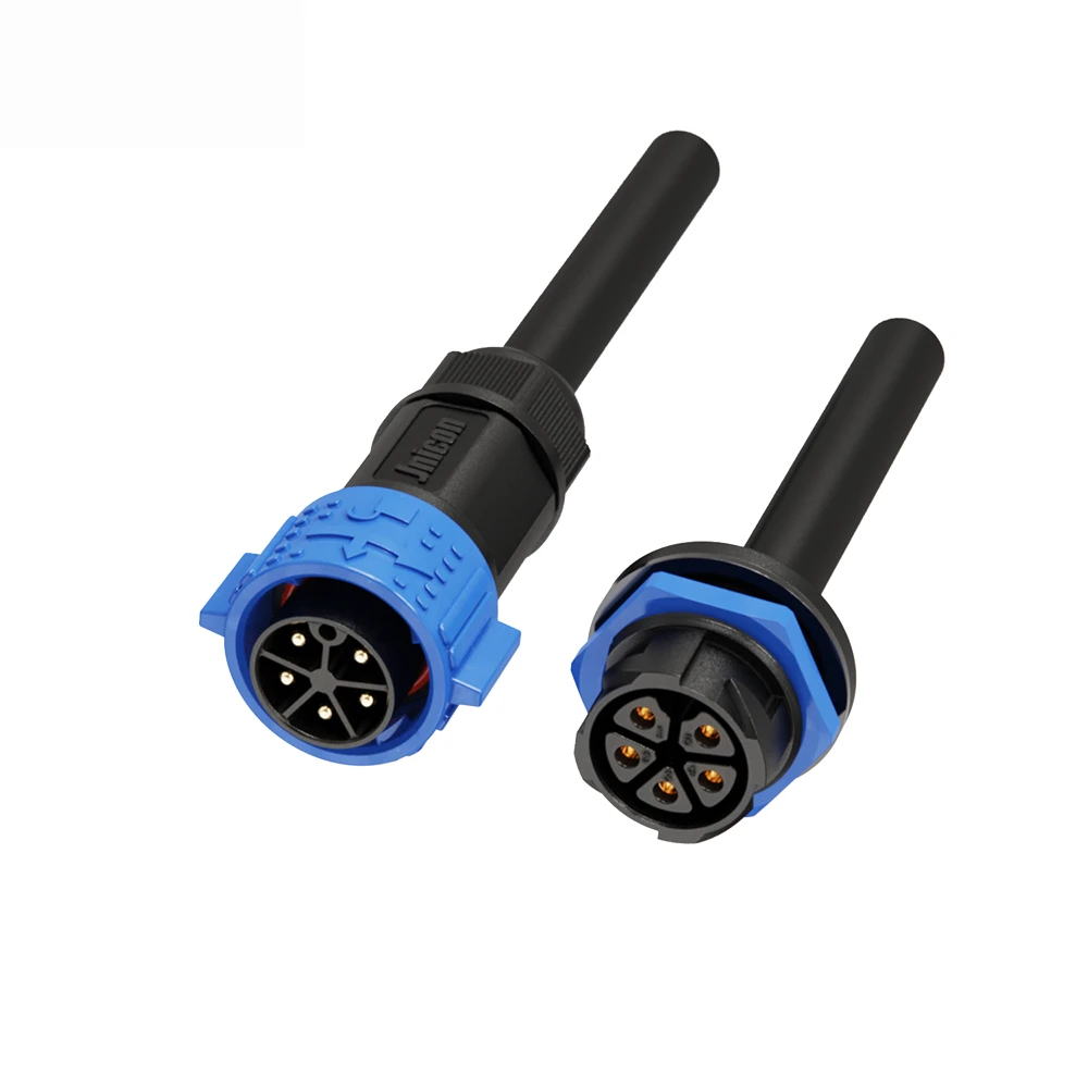
M25 5-Pin Waterproof Connector 30A Push Locking for LED Lighting & Marine
30A 5-pin push-locking waterproof power connector with IP67 protection for outdoor LED lighting and marine equipment.

MJ16 4-Pin Waterproof Connector 10A Quick Lock for Control Systems
10A quick-lock waterproof connector for control systems and automation equipment, with IP67 protection and reliable performance.
Related Industrial Solutions

Industrial Automation
Power, signal, and data connectivity for factory machines, robotic cells, sensors, and control cabinets. JNICON can review circular connectors and cable assemblies against motion, sealing, shielding, and maintenance requirements before prototype approval.
Explore Solutions
Rail Transit
Connector and harness options for rail equipment cabinets, auxiliary systems and monitoring interfaces. JNICON can review circuits, vibration, material requirements and maintenance with the OEM. Rail-specific approval must be confirmed for the exact part and installation, not inferred from industrial product ratings.
Explore Solutions
Marine & Offshore
Sealed power, signal and cable interfaces for marine equipment and offshore installations. Review salt exposure, condensation, vibration, cleaning and service conditions with JNICON. A stated IP68 rating does not by itself establish continuous subsea, pressure-depth or marine-class approval.
Explore SolutionsFAQ: Industrial Connector Vibration Testing
Conclusion: Qualify the Installed Connection
A useful industrial connectors vibration review connects the installed assembly to a defined exposure, a capable monitoring system and agreed acceptance criteria. Locking, cable support, fixture behavior and contact disturbance all deserve their own evidence. Keep the test report specific enough that another engineer can understand exactly what was evaluated.
Before releasing an OEM assembly, close the gaps between the purchase specification, the tested configuration and production controls. Retain failed-run evidence and document any corrective change. A passing development run should not become a broad claim about every model or installation.
Send JNICON your assembly drawing and vibration requirements for a model-specific technical review and quotation. Include cable routing, operating conditions, monitoring expectations and the evidence your project needs so the discussion starts with a reviewable requirement.