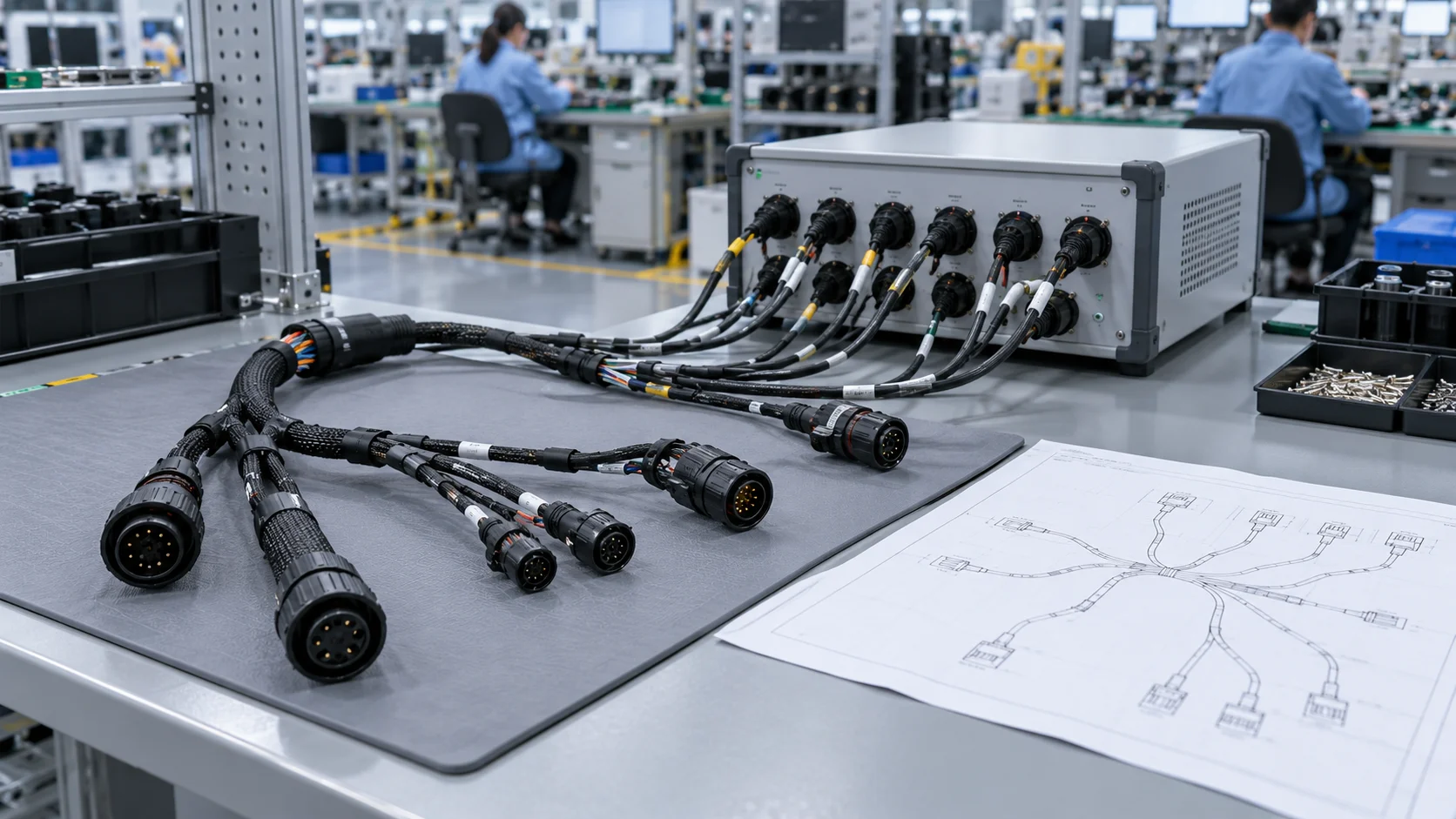
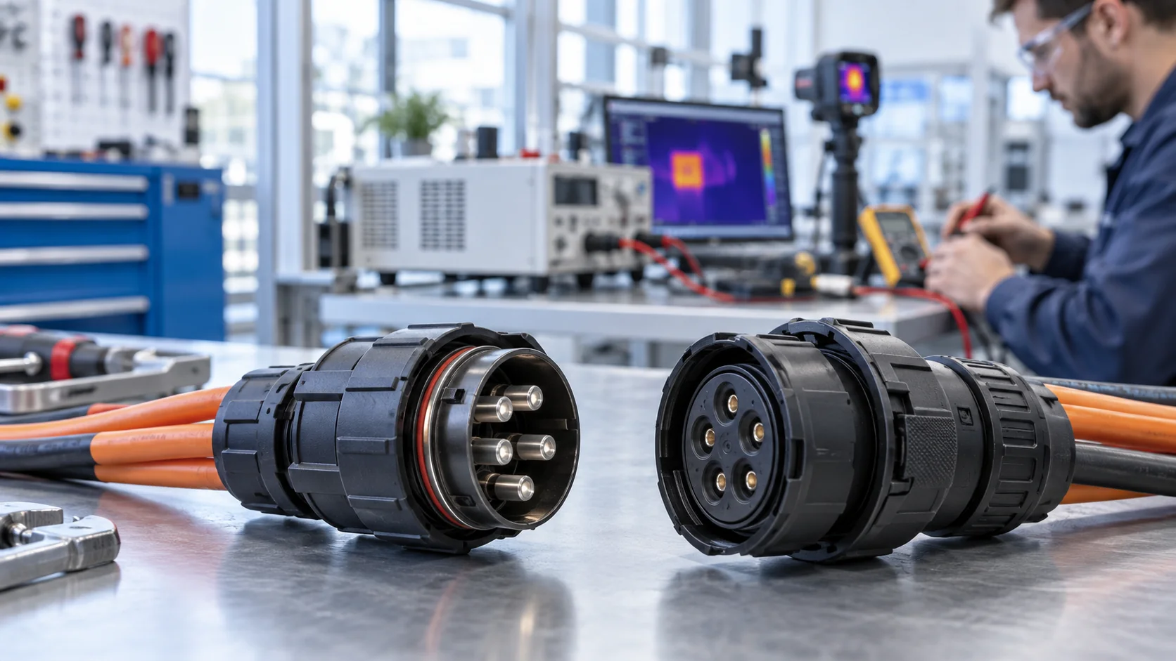
A quick disconnect connector may work perfectly during machine commissioning and become unreliable after repeated maintenance. Worn locking features, damaged seals, changing contact resistance, and poor handling can produce faults that a new-sample demonstration never reveals. Factory OEMs therefore need a defined qualification plan before treating a convenient connection as a dependable service interface.
This guide focuses on mating-cycle durability and locking retention for industrial equipment. It explains how to translate maintenance demand into a test specification, control the fixture, compare electrical and mechanical results, and request useful evidence from JNICON. It complements initial connector selection rather than repeating it. Test examples and illustrations are planning aids, not JNICON laboratory results, certified ratings, or universal acceptance limits.
What Does a Connector Mating Cycle Measure?
A mating cycle is a specified sequence of connecting and separating a compatible connector pair. For a locking interface, define whether the sequence includes full engagement, operation of the locking mechanism, intentional release, and complete separation. A carriage that merely touches the contacts without engaging the lock does not reproduce normal service.
The cycle count describes repetitions under stated conditions. It does not independently establish calendar life, vibration resistance, sealing after wear, or suitability for electrical disconnection under load. Those questions require their own evidence. Two reports claiming the same number of operations may describe different speeds, alignment, temperatures, lubrication, and inspection criteria.
Use the exact plug, receptacle, contact arrangement, cable construction, and mounting configuration intended for production. A result from a similar-looking family is not automatically transferable. Confirm whether the supplier's published endurance refers to contacts, the assembled pair, or a particular locking configuration.
For the earlier decisions about connector architecture and accessibility, read the quick disconnect connector selection guide for factory OEMs. Once the configuration is selected, qualification should verify the service operations that the finished machine will actually require.
Estimate Service Demand Before Choosing a Cycle Target
Start with the equipment maintenance model. Count planned module changes, cleaning disconnects, tooling changes, installation checks, commissioning operations, and reasonably foreseeable rework. Distinguish a connector opened annually from one opened whenever a production batch changes. The same machine can contain both service patterns.
As an illustrative calculation, an interface disconnected twice each operating week over five years and fifty operating weeks per year would accumulate 500 planned cycles. Add separately identified commissioning or repair events. This arithmetic estimates demand only. It does not establish a 500-cycle rating, prescribe a qualification margin, or demonstrate suitability for any JNICON model.
Agree on the target and margin with engineering, quality, and the supplier. Consider consequences of failure and whether the connector is replaceable during scheduled maintenance. Avoid choosing an impressive cycle number simply because a competitor advertises it.
Also record who performs the operation, available access, glove use, alignment visibility, and cable movement. Bench endurance can be satisfactory while an inaccessible machine location encourages operators to pull the cable or force a misaligned shell. A useful requirement connects the target count with a credible service method.
Separate Mechanical Endurance From Hot-Plug Capability
Rapid mechanical release does not mean an electrical interface can safely interrupt an energized circuit. A quick disconnect power connector requires an explicit assessment of voltage, current, stored energy, inrush, and the equipment's isolation procedure. Mechanical cycling must not be used as evidence of load-breaking capability.
The official scope of IEC 60512-9-1:2010, Test 9a describes a method for evaluating normal mechanical operation without electrical load when specified for the connector. Its scope is an important boundary: an endurance result under those conditions does not answer whether an energized machine may be disconnected.
Specify the applicable standard edition and detailed product requirements contractually. IEC 60512-1:2018 provides the general framework for connector tests and measurements; the relevant detail specification identifies the required tests, severity, and performance criteria. Referencing these publications does not claim that a JNICON product has been tested or certified to them.
Keep qualification specimens de-energized during mechanical operations unless an approved, appropriately controlled test explicitly requires otherwise. Any energized test needs competent personnel, suitable safeguards, and an application-specific procedure. Separate its results from ordinary mating-cycle evidence.
Freeze the Configuration and Acceptance Plan
Before cycling begins, issue a controlled specification that identifies both connector halves and the assembled cable configuration. Include contact plating where relevant, conductor termination, cable diameter, sealing components, panel mounting, and drawing revisions. Record approved substitutions rather than allowing the laboratory to choose convenient alternatives.
Define the sample plan and how samples represent production. State whether tests use multiple manufacturing lots, separately tested locking styles, or a single developmental configuration. A small prototype exercise can support design learning, but it should not be presented as broad production qualification.
| Requirement | Define before testing | Record during review |
|---|---|---|
| Operating sequence | Full engagement, locking, release, separation | Actual fixture sequence and deviations |
| Cycle conditions | Count, rate, dwell, temperature, cleaning policy | Completed cycles and interruptions |
| Mechanical checks | Force method, direction, limits, checkpoints | Measured values and visible wear |
| Electrical checks | Circuits, instrument method, limits | Baseline and checkpoint results |
| Final disposition | Failure rules and responsible approver | Release, investigation, or rejection |
Resolve acceptance limits before seeing the results. Changing a threshold after a specimen fails can hide a design problem. Where a limit remains unresolved, label it as an engineering action rather than inserting an unsupported value into the report.
At the review meeting, reconcile the specimen list with the approved bill of materials before interpreting graphs. Confirm that the same mating pair remained together throughout the sequence, and identify any replaced seals, contacts, or cables. Keep raw readings alongside the summary so an unexpected trend can be checked rather than averaged away. Separate completed tests from pending checks, and give every open deviation an owner and a release decision. If the application later changes its maintenance frequency, mounting orientation, cable support, or cleaning method, assess whether the original qualification still represents service conditions. This configuration review is often more useful to an OEM than a cycle total quoted without its test boundaries.
Build a Fixture That Reproduces Normal Mating
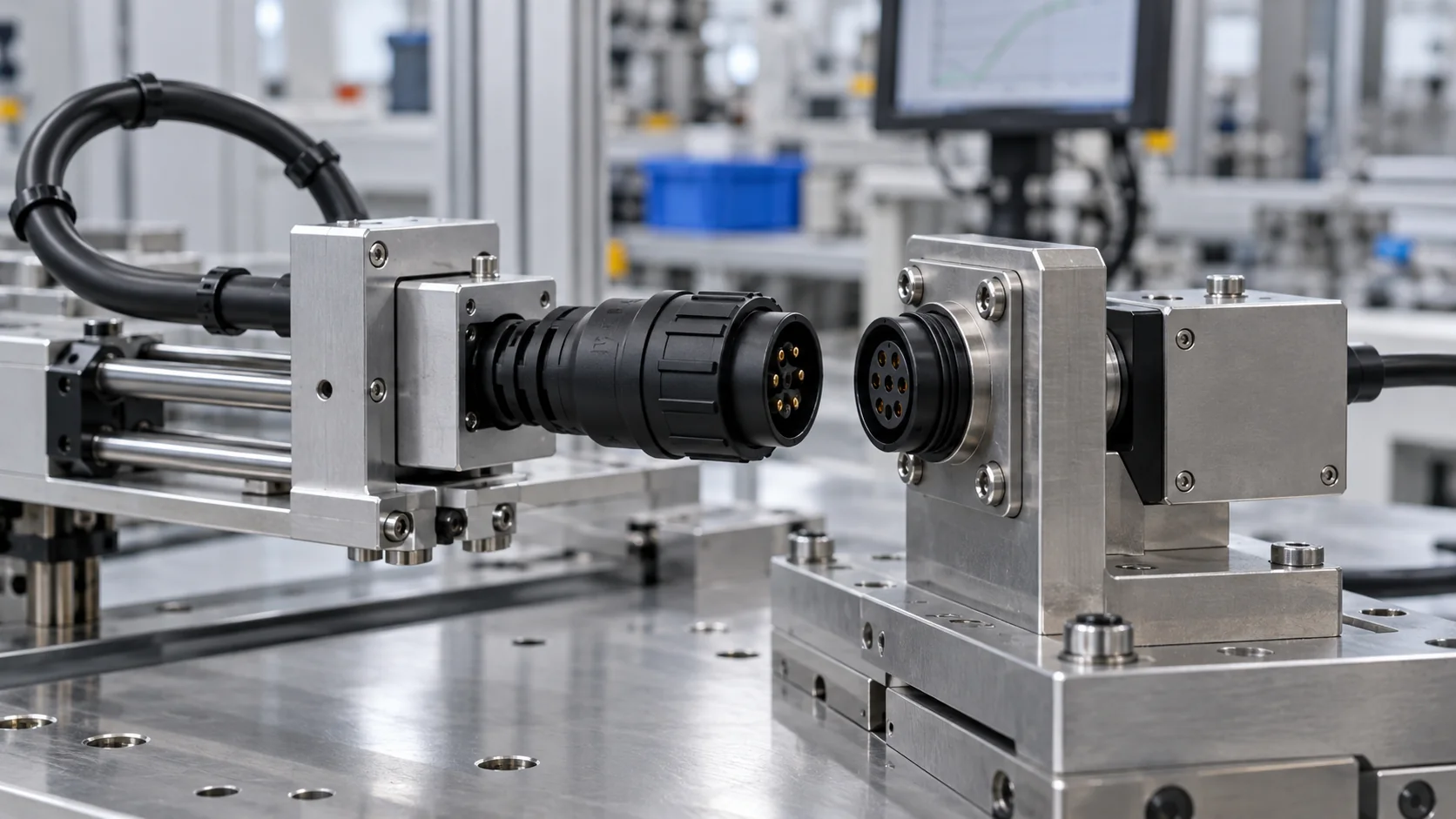
The fixture should align the mating faces and support the intended mounting arrangement without distorting the housings. Apply operating movement through appropriate structural features. Do not make the cable carry the entire carriage force unless the approved service method specifically requires that loading.
For panel-mounted quick disconnect electrical connectors, reproduce the panel thickness, mounting hardware, and cable support when these influence alignment or shell movement. A rigid laboratory clamp can conceal flexibility in the actual installation. Conversely, a poorly aligned fixture can create wear that would not occur in a correctly mounted machine.
Provide controlled travel, engagement confirmation, and the required lock-release action. Record how the setup prevents partial mating, excessive overtravel, side loading, and unintended rotation. Use a service loop that allows movement without repeatedly bending a short cable at its entry.
Inspect the fixture as well as the specimen. Adapters, alignment guides, and grip pads can wear during the test. If measured force suddenly changes, investigate the setup before attributing the change to connector durability. Retain fixture identification and photographs with the test record so another engineer can understand the loading path.
Measure Mating Force and Locked Retention Separately
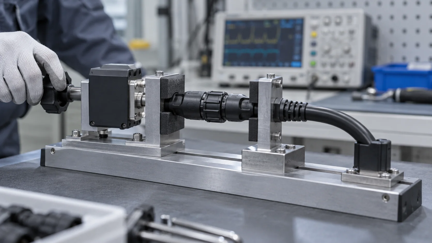
Mating force describes the effort required to engage the pair under a defined operating method. Unmating force after intentional release describes a different operation. Locked retention evaluates resistance to separation while the locking mechanism remains engaged. Combining these measurements into one generic pull test makes the result difficult to interpret.
For push-lock interfaces, define how the release sleeve or latch is operated. For bayonet interfaces, define the required rotation and final locked position. An audible click can support operator feedback, but it is not a substitute for documented engagement and retention criteria.
Specify the load direction, application rate, duration, measurement location, and permissible movement. Restrain the appropriate connector features and support the cable. A cable pull-out test evaluates cable retention or termination behavior; it does not necessarily evaluate the connector-to-connector lock.
Compare baseline and checkpoint values using the same setup. Watch for declining retention, increasing engagement effort, latch deformation, incomplete seating, or erratic release behavior. Identify which observations require stopping the test. JNICON enquiries should request model-specific evidence and agreed limits rather than assume that every quick disconnect connector shares one retention force.
Track Electrical Stability at Defined Checkpoints
Mechanical survival alone is insufficient when the interface carries power or control signals. Measure the electrical characteristics relevant to the application before cycling, at agreed checkpoints, and after the final operation. Identify each circuit and measurement path so changes can be traced to a specific contact pair.
Where low resistance matters, a suitable four-wire measurement can reduce the influence of test leads. The procedure must still define measurement current, connection points, instrument capability, fixture contribution, and acceptable variation. Do not apply an arbitrary milliohm limit to every connector or confuse whole-harness resistance with contact-interface resistance.
For sensitive controls, define any permitted discontinuity and the monitoring method during the approved mechanical or environmental test. A static reading after the pair settles may miss an intermittent event. Conversely, fixture movement can create false failures if monitoring leads are unsecured.
Use the cable assembly pinout and intermittent-fault testing guide when the connector is part of a finished harness. Correct mapping, isolation, fixture checks, and circuit identification remain essential. A connector endurance test should not accidentally approve a cable assembly with the wrong pinout.
Inspect Wear, Seals, and Locking Features
Schedule visual inspections at the same checkpoints used for force and electrical measurements. Look for damaged keys, cracked housings, deformed latches, loose mounting hardware, displaced seals, contact contamination, and unusual debris. Record findings before cleaning or disassembly changes the evidence.
Photographs should identify the sample and inspection stage. Consistent views and lighting make progressive wear easier to compare. If examination requires dismantling the specimen, define whether that specimen may return to cycling or should be reserved for investigation. Reassembly can change contact alignment or sealing behavior.
Do not describe every visible mark as failure. Some cosmetic wear may be acceptable under the product specification, while a subtle locking defect can be functionally serious. Connect observations to the approved criteria and service consequences instead of relying only on appearance.
Cleaning, lubrication, and seal replacement must follow the agreed procedure and product instructions. An undocumented application of lubricant can improve force readings while invalidating comparison with dry service. Likewise, cleaning contacts immediately before every reading may conceal a contamination problem that the factory installation will not avoid.
Check the Environment After Repeated Service Operations
A new connector's environmental rating does not automatically describe a worn assembly after repeated servicing. If water, dust, vibration, or temperature exposure is part of the application, define how those stresses combine with mating cycles. The order can matter: cycling before an environmental test asks a different question from cycling a previously exposed specimen.
State whether sealing is evaluated fully mated, unmated with a specified cap, or in another approved configuration. Include cable entries and panel interfaces in the scope when the finished assembly depends on them. Do not assume that a connector face rating covers the complete machine enclosure.
A laboratory endurance sequence also cannot reproduce every operator mistake. Separately review keying, access, labeling, storage of disconnected ends, and protection from contamination during maintenance. These controls can prevent misuse without changing the connector's underlying rating.
For power applications, wear-related resistance changes may deserve a separate loaded thermal evaluation under the actual installation conditions. The high-current connector overheating and voltage-drop guide explains why current, contact resistance, and the assembled installation must be considered together. Do not treat mechanical cycling as a substitute for that assessment.
Use Failure Rules That Preserve Useful Evidence
Specify when a test stops and who decides whether it can resume. Examples of conditions needing review include inability to lock, unintended separation, unacceptable electrical change, housing damage, or a fixture fault. The exact thresholds belong in the approved plan, not in an improvised operator decision.
Record the cycle count, sample identity, last successful checkpoint, operating conditions, and observed failure. Preserve event logs and photographs. Do not repeatedly remate the pair until it passes and then report only the successful reading. That practice removes the evidence needed to understand an intermittent fault.
Distinguish specimen failure from test interruption. A damaged fixture, interrupted power supply to the tester, or instrument issue does not necessarily condemn the connector. However, it may invalidate part of the sequence. Document the investigation and the justified restart or replacement decision.
After a design or process change, decide which tests must be repeated. A revised seal, contact material, latch geometry, termination, or cable support can affect earlier results. Keep change control connected to qualification records so a later production version is not released using evidence from a materially different assembly.
Turn Qualification Results Into Production Controls
Design qualification and routine production inspection serve different purposes. A lengthy endurance sequence may consume or alter samples; it is not automatically an appropriate test for every shipped connector. Production controls should verify the features that keep the qualified configuration consistent.
Agree on dimensional checks, locking engagement checks, assembly workmanship, electrical screening, and any required sampling. For quick disconnect wire connectors supplied as cable assemblies, include termination, strain relief, cable entry, and drawing revision. Record how nonconforming units are contained and released after rework.
Define incoming inspection around the purchase specification. Receiving personnel need compatible mating parts and controlled instructions, not an undocumented tug test that can damage an acceptable unit. Confirm whether supplied reports cover a batch, qualification samples, or individual assemblies.
Use production feedback to revisit the service assumptions. Unexpectedly frequent maintenance, contamination, or forced handling can increase actual demand beyond the original estimate. Track field returns by assembly revision and service history where available. A connector chosen for occasional access may need a different maintenance strategy when the machine's operating model changes.
Send JNICON a Mating-Cycle Qualification RFQ
A useful RFQ identifies the intended interface and the unresolved engineering decisions. Send compatible part numbers or a proposed connector family, contact count, electrical function, cable dimensions, mounting details, and a drawing of the available service space. Add photographs of the installation when they clarify access and support.
Provide the expected service operations and estimated lifetime cycle demand. State the proposed locking method, environmental exposure, cleaning policy, and whether the equipment is isolated before disconnection. Identify any application-specific standard or customer requirement without assuming general product approval.
Then request the available evidence for the exact configuration: endurance conditions, force measurements, electrical checkpoints, environmental sequence, sample scope, and reporting format. Ask JNICON to identify which requirements can be supported by existing documentation and which need project-specific confirmation. Do not infer a cycle rating from a product photograph or catalogue locking description.
Include prototype quantity, forecast production volume, delivery stages, and change-control expectations. This lets engineering and purchasing compare quotations on equivalent scope. An agreed connector configuration and acceptance plan should precede volume release, with open requirements clearly assigned rather than hidden behind a generic claim of durability.
Related Products

M19 3 Pin Waterproof Connector 15A Push Locking IP67 for Industrial Automation
15A 3 pin push-locking waterproof circular connector with IP67 rating for industrial automation and power distribution.

M19 9 Pin Signal Waterproof Connector 5A Push Locking IP67 for Sensor Networks
5A 9-pin push-locking waterproof signal connector with IP67 rating for sensor networks and control system data transmission.
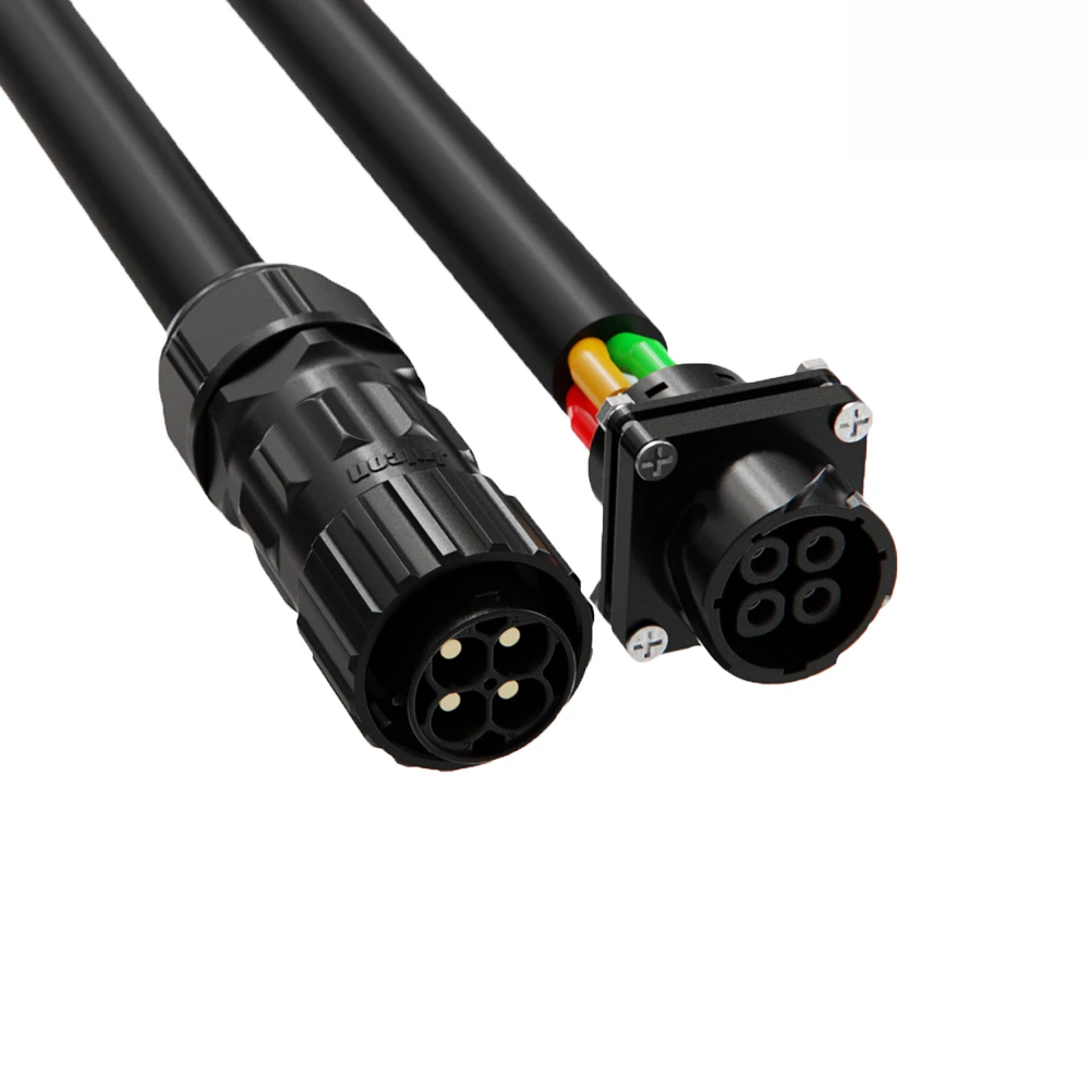
M28 4 Pin Waterproof Connector 60A Bayonet Locking IP67 for Power Systems
60A 4-pin bayonet-locking waterproof circular connector with IP67 rating for industrial power distribution and solar applications.
Related Solutions

Industrial Automation
Power, signal, and data connectivity for factory machines, robotic cells, sensors, and control cabinets. JNICON can review circular connectors and cable assemblies against motion, sealing, shielding, and maintenance requirements before prototype approval.
Explore Solutions
Rail Transit
Connector and harness options for rail equipment cabinets, auxiliary systems and monitoring interfaces. JNICON can review circuits, vibration, material requirements and maintenance with the OEM. Rail-specific approval must be confirmed for the exact part and installation, not inferred from industrial product ratings.
Explore Solutions
Outdoor Lighting & LED
Power and control connections for outdoor luminaires, architectural lighting and LED installations. JNICON can review connectorized cables, locking styles and sealing arrangements against driver loads, cable dimensions, weather exposure and maintenance needs.
Explore SolutionsFrequently Asked Questions
Conclusion: Specify the Service Life You Need
Qualifying a quick disconnect connector requires more than counting movements. Define the real service sequence, reproduce its mounting and alignment, distinguish mating effort from locked retention, monitor electrical stability, and inspect seals and locking features at controlled checkpoints. Environmental and energized-operation requirements need separate, explicit evidence.
For factory OEMs, the next step is a documented discussion of the exact connector and cable assembly. Share your service-cycle estimate, drawing, installation conditions, and evidence requirements through the JNICON inquiry and contact page. Request an engineering review and quotation that identify the proposed configuration, supported test scope, and any requirements still needing confirmation before production.