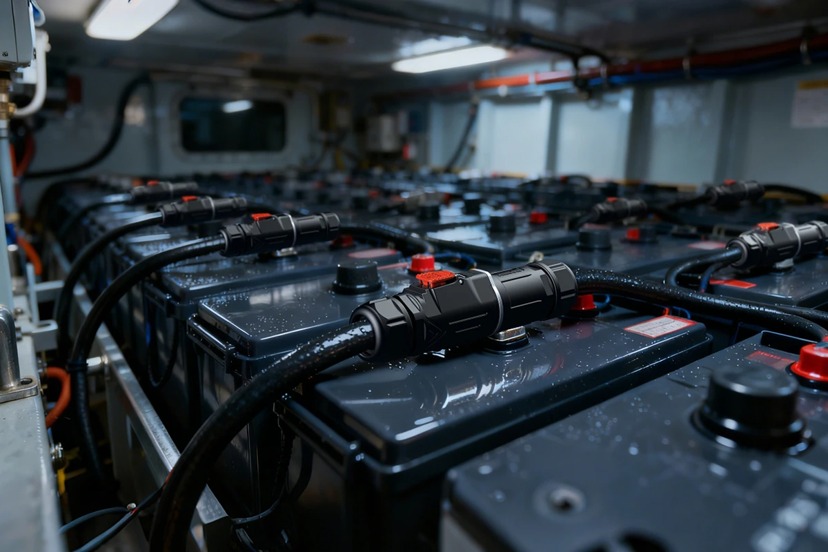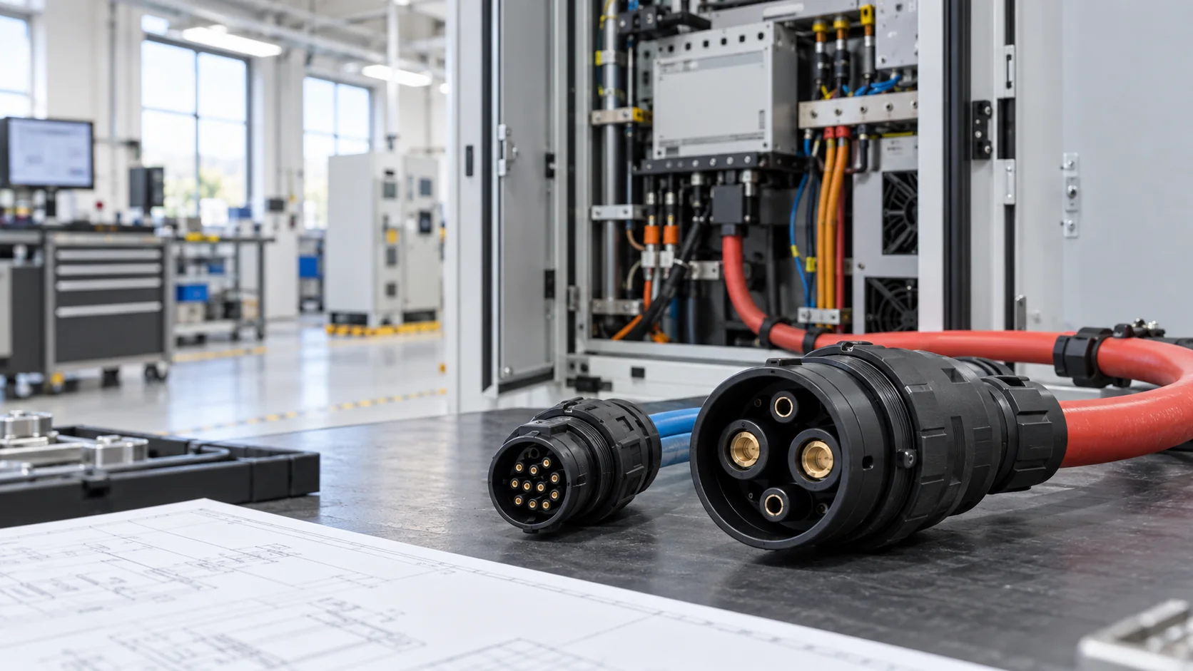
A high current connector that runs hot in a factory machine is rarely fixed by choosing a larger number on a catalog page. Heat can originate at the contact interface, a crimp, a conductor, or a poorly ventilated enclosure. This OEM checklist explains how to locate the loss, measure temperature rise on the finished assembly, and set a repeatable acceptance test before production. It is written for engineers specifying EV chargers, energy-storage cabinets, power distribution, and industrial equipment—not for troubleshooting energized hardware without a qualified technician. It also separates supplier claims from test evidence and specifies the information needed for a useful quotation.
Start With the Hot Spot, Not the Catalog Ampere Value
Before changing a connector, map where the temperature is rising. A warm plug shell, a hot cable exit, and one overheated pin point to different mechanisms. Capture a thermal image only after the assembly reaches a stable operating condition, and confirm suspicious points with a calibrated contact sensor. Shiny metal, changing emissivity, and reflected heat can make infrared images misleading. Record ambient temperature, current, duty cycle, enclosure condition, airflow, and the time since energization alongside each image.
Compare like-for-like circuits. If one pole is markedly hotter than adjacent poles carrying similar current, inspect that termination and its mating contact before replacing the entire connector family. If every pole and the cable are warm, investigate system loading, conductor cross-section, derating, and cabinet ventilation. A hot mating face can indicate contact resistance, incomplete engagement, contamination, or wear. A hot strain-relief area often suggests conductor or crimp loss.
Do not unplug, retorque, or remake the assembly while it is energized. Follow the site's isolation procedure and use qualified personnel. The goal is an evidence trail: a labeled thermal map, measured currents, a circuit drawing, sample serial numbers, and photos of the exact installed configuration. JNICON can use this evidence to narrow a technical review before proposing a different high current connector or cable assembly.
Why Small Resistance Changes Become Thermal Problems
Electrical loss rises with the square of current: P = I²R. At 100 A, an extra 1 mΩ produces 10 W of localized heat. The equation is simple, but connector failures are not. The measured resistance includes the mated interface, terminal, termination, and nearby conductor. It changes with temperature, contact force, vibration, and aging. A single room-temperature milliohm reading is therefore not a full qualification result.
Start with the manufacturer’s actual rating conditions rather than treating an ampere value as universal. Ask for the conductor size, number of energized poles, allowable temperature rise, ambient condition, and test arrangement behind the rating. A compact multi-pole housing may retain more heat than one isolated contact. Adjacent power and signal circuits can also change the thermal profile. If a cable is undersized, the conductor can feed heat back into an otherwise sound contact.
IEC 60512-5-1 describes temperature-rise testing for electromechanical components, while IEC 60512-2-1 covers contact-resistance measurement. Use the applicable procedure and project specification; do not assume that citing a test standard alone proves suitability for a particular machine. See the official temperature-rise test reference and contact-resistance reference when drafting the validation plan.
Define the Real Load and Derating Envelope
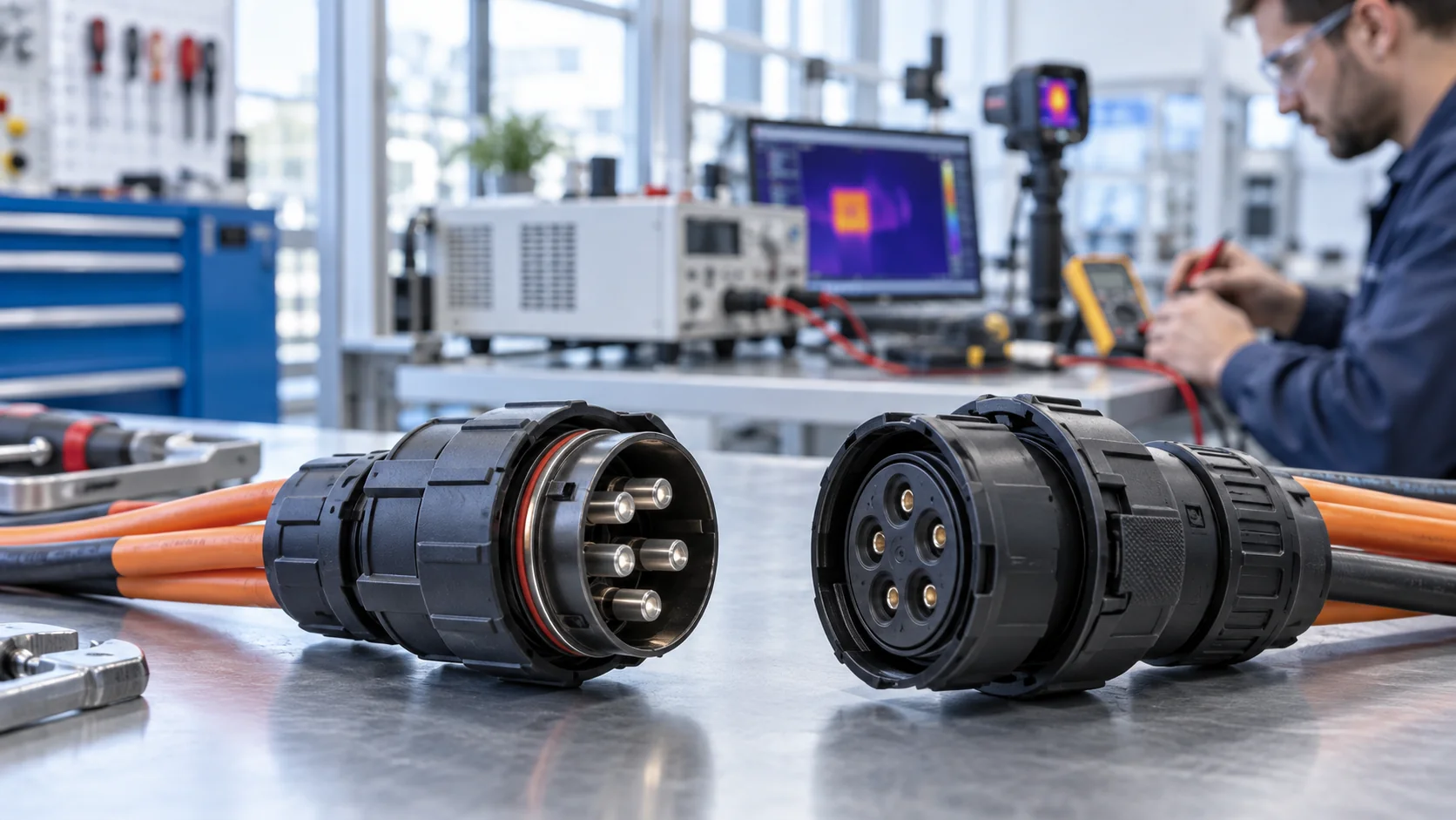
An OEM load case should describe more than nominal current. Document continuous current, peak duration, repetition rate, startup surge, and simultaneous loading across every pole. Note the hottest expected ambient temperature inside the enclosure—not only the climate outside it. Include airflow, mounting orientation, bundle density, nearby heat sources, altitude if relevant, and the expected cable length and gauge.
A charger or storage system may operate at modest average power yet hold a high output for long enough to reach thermal equilibrium. A robotics line may see short bursts with repeated reconnects and vibration. Each scenario asks a different question of the connector. Define both normal operation and credible abnormal operation, such as a blocked vent or a partially loosened cable gland, but keep fault protection as a separate system design task.
Ask each supplier to show how it derates the selected configuration. A high current connector rating should be tied to the supplied terminal, plating, housing, cable, crimp tool, and test method. Changing any of those can invalidate a previous thermal result. JNICON’s power connector range provides starting candidates; final selection should follow the actual circuit and installation envelope, not a generic product-family headline.
Measure Temperature Rise on the Finished Assembly
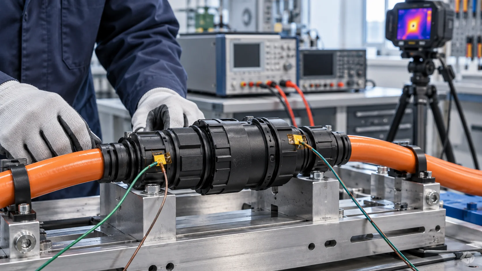
Test a complete, representative assembly rather than a bare contact in isolation. Use the production cable gauge and length, approved terminal, crimp setting, seal, backshell, and enclosure arrangement. Put measurement points at the mating interface, both terminations, cable exits, and an ambient reference. Photograph the setup so another lab can repeat it. If several poles carry current, energize them as the machine will, not one at a time merely to obtain a favorable result.
Record current and voltage throughout the run. Continue until the chosen stability criterion is met; a quick reading after startup can miss the worst case. Report both absolute temperature and temperature rise above local ambient. Then compare the outcome with component limits, cable insulation limits, operator-touch requirements, and the OEM’s own acceptance criteria. Never infer a safe limit from a single photo or a supplier's marketing sheet.
Repeat the test after assembly changes and on samples from more than one build lot when the risk justifies it. A thermal pass does not replace dielectric, insulation, IP, or mechanical checks. Conversely, an IP pass does not prove thermal performance. Ask JNICON for the configuration and test evidence relevant to your project, and use that evidence to design your validation—not to skip it.
Separate Contact Resistance From Cable Loss
Use a four-wire measurement method when you need to resolve very small resistance changes. Place sense points consistently and document their locations; otherwise readings from different builds cannot be compared. Measure the mated interface and termination path separately where the geometry permits. Record readings before thermal cycling, after thermal cycling, and after repeated mating or vibration. The trend often matters more than one initial value.
If resistance rises only at one contact pair, inspect plating condition, contamination, mating depth, spring force, and pin damage. If the cable-side drop is high, review strand size, crimp barrel selection, stripping length, tool calibration, and conductor condition. A visually neat crimp can still be electrically weak. Section the joint or run a pull test when the production process or failure analysis warrants it.
For a harness, include cable routing and strain in the investigation. Tight bends near a connector, unsupported weight, and repeated flexing can gradually change the contact or termination load. Our custom cable assembly guide explains why connector and harness specifications should be reviewed together. The corrective action should address the identified loss path, not merely increase the nominal current rating.
Audit the Termination and Cable as One System
Many field overheating reports are really process-control problems at the cable termination. Verify that the approved conductor material, strand class, cross-section, insulation diameter, and terminal barrel match the drawing. Check the stripping process for nicked strands or incomplete insulation removal. Confirm the crimp tool, die, locator, and calibration record used on production units. A laboratory prototype made with a different tool is not adequate proof of repeatability.
Specify objective checks: crimp-height or dimension limits where appropriate, visual criteria, pull-force test, continuity, and millivolt-drop or resistance testing under a defined load. Retain serial or lot traceability between connectors, terminals, cable, and test records. If soldering is part of the approved design, assess wicking, heat damage, and strain relief rather than assuming solder is automatically more reliable.
High-current cables can be heavy and stiff. A cable gland, overmold, or clamp must carry mechanical load without pushing the terminal off-axis. A sealed backshell can help environmental protection while still needing clearance for bend radius and service access. JNICON should be asked to quote the complete assembly configuration, including conductor and termination details, so the customer can compare an equivalent tested build rather than unrelated catalog components.
Check Mating, Locking, Plating, and Wear
A connector can pass a bench test and run hotter in service if it is not fully mated. Confirm keying, lock engagement, insertion force, and any secondary retention required by the installation. Train the production line to verify the locked state, and make that state visible or measurable where possible. Avoid using cable tension as an implicit lock. After repeated service cycles, inspect contact surfaces for wear, oxidation, and debris.
Plating and contact geometry are part of the electrical design. Ask the supplier what mating-cycle expectation and environmental exposure apply to the exact terminal option. Do not mix visually compatible parts from different families without compatibility evidence; a mechanical fit can hide different contact-force or sealing behavior. If the application experiences shock or vibration, validate after the specified test and then remeasure resistance and temperature rise.
For power-distribution equipment, serviceability may matter as much as first-build performance. A positive lock can reduce partial disengagement; a poorly accessible connector can invite incorrect reassembly. Involve maintenance staff in the mock-up review. The best high current connector is the one that can be installed, inspected, and replaced consistently in the customer’s machine, within the thermal and mechanical design envelope.
Do Not Confuse Sealing With Thermal Capacity
IP protection and current capacity solve different problems. A connector may resist dust or water ingress in a specified test yet still overheat when installed in a tight enclosure at sustained load. Seals, overmolds, and backshells can change airflow and heat rejection. Water that enters through a damaged cable jacket or an incorrectly assembled gland can also create corrosion and raise resistance over time.
Validate the exact assembly as shipped. Check seal size against cable outside diameter, compression after repeated mating, gland torque or locking procedure, and whether the test included the same backshell and cable. If washdown, condensation, or outdoor cycling is expected, define those conditions explicitly. Our condensation versus leakage guide helps distinguish water-path diagnosis from thermal diagnosis.
A sealed design should be tested for both ingress and temperature rise, followed by a post-exposure electrical check where risk warrants it. Do not report an IP grade as a blanket guarantee against overheating. When selecting a JNICON power connector, share the ambient profile, enclosure details, and cleaning or outdoor exposure, so the team can review sealing and heat management together.
Qualify After Vibration, Cycling, and Reassembly
Qualification should mimic the lifecycle that creates field failures. For a stationary cabinet, include realistic thermal cycling and service reassembly. For mobile machinery or charging equipment, add the project's vibration, shock, and mating-cycle profile. Recheck lock engagement, contact resistance, insulation condition, and temperature rise after exposure. A connector that passes only when new may not be the right choice for a maintainable OEM platform.
Define a sample plan and acceptance criteria before testing. Record baseline measurements, the sequence of stress tests, and the same electrical measurements afterward. If a sample fails, preserve it for inspection rather than quietly replacing it and restarting. A clear failure-analysis record improves both design correction and supplier accountability. Distinguish between design-qualification samples and ongoing production checks; neither substitutes for the other.
Where the assembly will be repeatedly disconnected, consider protective caps, cleaning instructions, and replacement triggers. For installations subject to vibration, check strain relief and mounting as a system. JNICON can discuss connector options and assembly details, but the OEM remains responsible for confirming the final operating profile and for establishing a maintenance interval appropriate to the equipment.
Choose a JNICON Candidate by Circuit Architecture
After identifying the loss mechanism, shortlist connectors by actual circuit architecture. A two-pole high-current path may suit a different family from a mixed power-and-signal interface. The MJ32 2-pin 120A quick-lock product is a candidate to examine for a two-pole charging interface; its advertised rating is not a substitute for the OEM’s own cable and thermal validation. A larger M40 option or an M28 3-pin configuration may fit other layouts, depending on phase count, conductor size, space, and service pattern.
Compare candidates in a matrix: pole count, rated voltage and current under stated conditions, terminal size, cable range, lock style, IP configuration, mating cycle, mounting method, and documented tests. Record which requirements are verified, pending, or not applicable. Avoid calling a component “equivalent” merely because it shares an ampere rating or shell diameter.
JNICON’s new-energy selection guide and EV charging connector guide provide related application context. The next decision is sample validation against your real duty cycle and installation. That is where supplier specifications become an OEM-approved design.
Write an RFQ With Testable Acceptance Criteria
A good RFQ lets engineering and purchasing compare like with like. Send a circuit drawing with pin assignments and polarity, continuous and peak current per pole, operating voltage, cable gauge and outside diameter, target length, connector orientation, mounting envelope, ambient range, and ingress or vibration exposure. State whether the part is a loose connector, pigtail, overmolded assembly, or complete harness.
Then specify the evidence you expect: current-rating conditions, material and plating specification, temperature-rise method and limits, contact-resistance baseline and post-stress limit, cable pull-force requirement, IP configuration, and traceability format. Ask for sample quantity, tooling assumptions, lead time, change-control process, and production test coverage. Where a standard applies, cite its exact edition and the clause or test condition in the project specification.
Share any measured overheating case with photos and data rather than just saying “the connector gets hot.” An anonymized thermal map, current trace, assembly drawing, and returned sample can shorten diagnosis. Ask JNICON to identify the proposed configuration and any open validation items in writing. This makes an initial technical review useful and gives the OEM a documented path from failure observation to controlled production acceptance.
Turn Qualification Data Into Production Controls
Once the prototype passes, translate the evidence into a controlled bill of materials and work instruction. Lock the connector body, terminal part number, contact plating, cable type, approved crimp tool, die, setting, seal, and backshell. Define what may be substituted and what requires a new engineering review. Otherwise a seemingly minor purchasing change can alter resistance or heat rejection without anyone repeating the thermal test.
For incoming material, verify identity and critical dimensions. For assembly, record operator, tool calibration, crimp result, continuity, and the lot or serial number needed for traceability. A production line usually cannot run a full thermal qualification on every unit, so choose practical surrogate controls, such as crimp dimensions and electrical resistance, that correlate with the validated design. Periodically audit those controls against a complete assembly test.
Use a change notice for terminal, conductor, plating, supplier, tooling, or housing changes. If a customer later reports overheating, trace affected lots and compare the returned unit with qualification samples. This is the difference between a one-time “passed test” and a reliable OEM supply process. Ask JNICON what documentation and production checks can be supplied with the quoted assembly, and record any gaps before purchase approval.
Conclusion: Verify the Full Current Path
An overheating high current connector is a system problem until measurement proves otherwise. Map the hot spot, test the finished cable assembly under the real duty cycle, separate contact loss from conductor and termination loss, and repeat key measurements after environmental stress. Treat catalog ratings and IP grades as inputs to the validation plan, not as its conclusion.
JNICON can help OEM teams shortlist power connector and cable-assembly options for EV charging, energy storage, and industrial equipment. Send your drawing, load profile, cable specification, thermal evidence, and target acceptance criteria through the JNICON inquiry page to request a technical review and quotation. State any known failure mode so the discussion begins with the actual operating risk.
Related High Current Connector Products
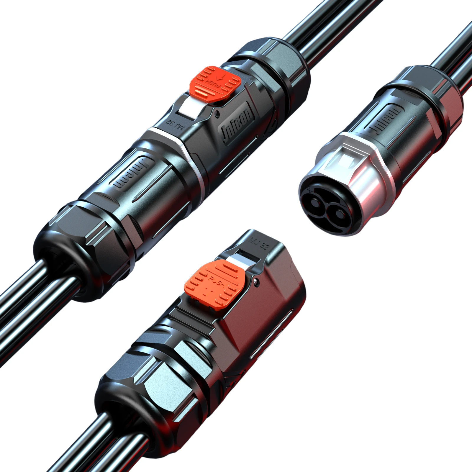
MJ32 2-Pin Waterproof Connector 120A Quick Lock for EV Charging
120A quick-lock waterproof connector for EV charging and energy storage, with IP67 protection and silver-plated contacts.
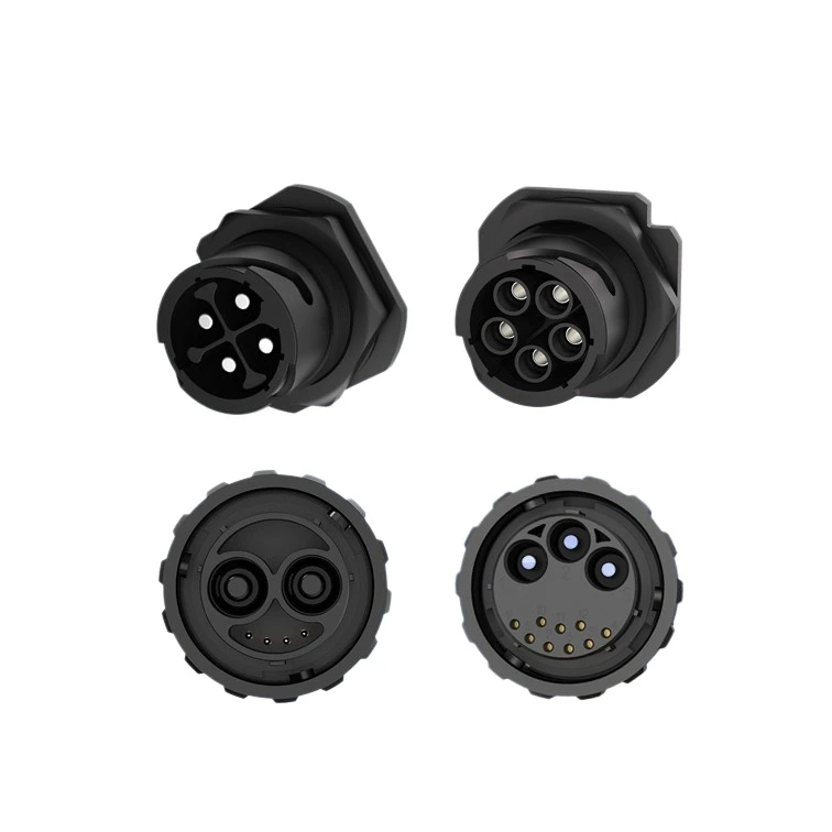
M40 4-Pin Waterproof Connector 120A Bayonet Lock for EV Charging
120A bayonet lock waterproof connector for EV charging and energy storage, with IP67 protection and reliable power transmission.
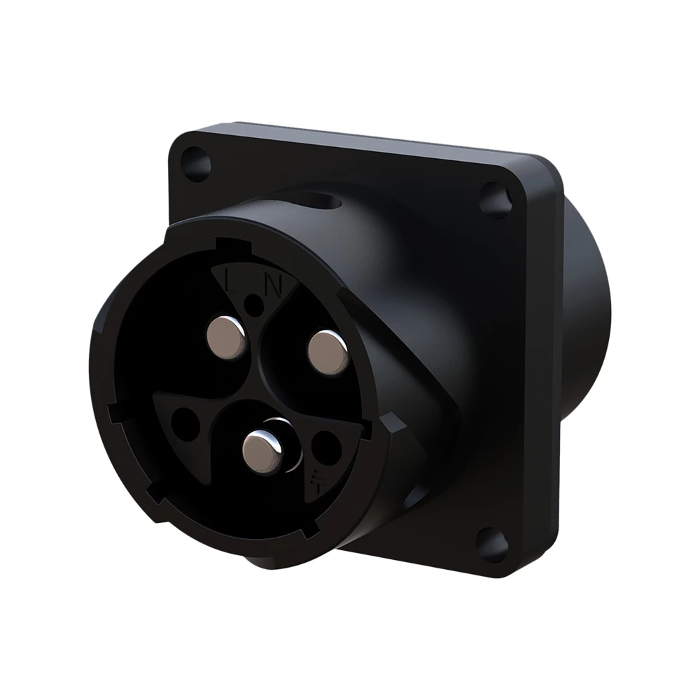
M28 3-Pin Waterproof Connector 80A Bayonet Locking IP67 for Solar & Storage
80A 3-pin bayonet-locking waterproof circular connector with IP67 rating for solar photovoltaic and energy storage systems.
Related Industrial Solutions

New Energy & Energy Storage
Safeguarding high-capacity grid infrastructures with certified high current connectors engineered to withstand massive voltage loads, minimize thermal buildup, and eliminate systemic arcing risks from cell to grid container.
Explore Solutions
Solar & Photovoltaic
Engineered for 1500V DC utility-scale solar farms and smart PV tracking systems. Our TUV/UL certified connectors eliminate DC arcing risks and withstand persistent UV degradation and sandstorms in desert environments.
Explore Solutions
Industrial Automation
Empowering smart factory infrastructures with certified power, signal, and data connectors. Engineered to withstand continuous multi-axis robotic motion, eliminate electromagnetic interference (EMI), and ensure zero-downtime performance in harsh manufacturing environments.
Explore Solutions