A splitter module can simplify an OEM wiring layout, but a convenient T or Y shape does not establish current capacity, circuit protection or data compatibility. This guide explains how to specify passive electrical branch assemblies, calculate shared loads, document pin assignments and validate the finished harness before production.
Define What Your Splitter Module Must Actually Do
Start with an electrical function, not a photograph. In this guide, a splitter module means a passive connectorized distribution junction or T/Y cable assembly used to route defined industrial power or signal circuits. It is not an optical PLC splitter, an Ethernet switch, a USB hub or a PoE conversion device. Those products perform different functions and require their own specifications. A similar-looking housing does not make them interchangeable.
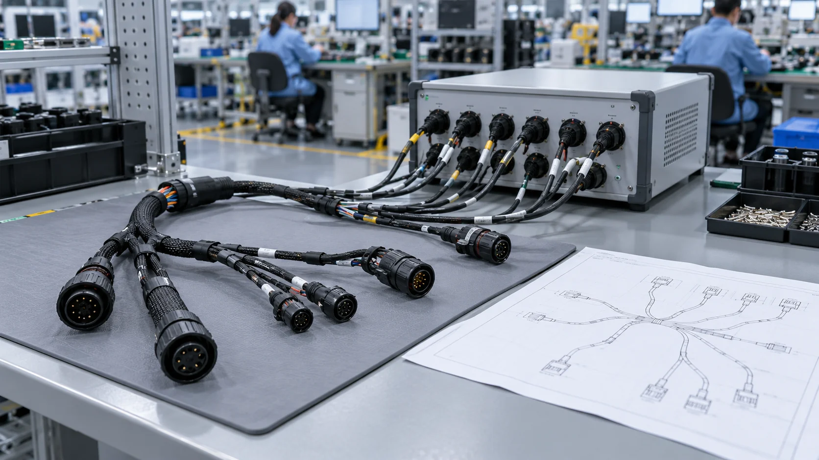
JNICON lists splitter cable assemblies within its cable assembly range and offers drawing-based multi-branch harness work. That establishes a relevant starting point for an OEM inquiry, not approval of every possible circuit. Specify whether each incoming conductor is shared between branches, passed through to only one outlet or connected to a dedicated return. Ask for the exact connection diagram before choosing a connector family.
Also decide what must happen when a branch is disconnected or fails. A passive junction normally does not diagnose a fault or isolate an overloaded output unless additional components are expressly included. Document required fusing, isolation, switching and status indication separately. Qualified electrical personnel should review hazardous-voltage or safety-related circuits against the applicable equipment requirements before a harness is released.
Choose T, Y or Multi-Branch Geometry from the Installation
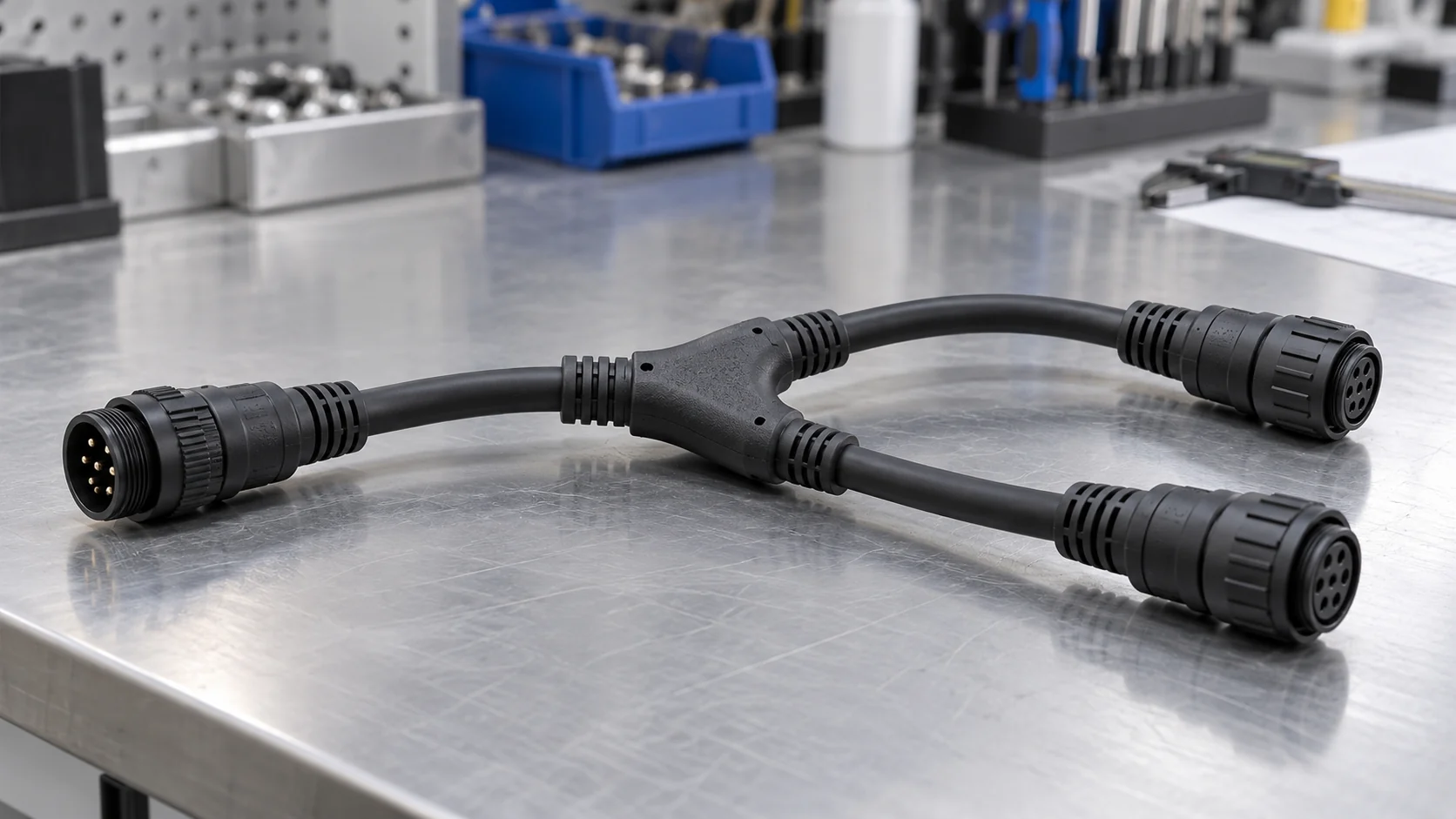
A T configuration can suit a main cable route with a perpendicular drop. A Y configuration can suit two outgoing paths that separate gradually. A multi-branch harness may reduce repeated connector pairs but makes the junction and individual branches harder to replace independently. These are packaging choices. None of the shapes establishes a particular electrical connection or current rating.
Mark the actual equipment envelope on a layout drawing. Include the trunk entry direction, branch exit angles, mounting points, connector engagement space and the service technician's access. Measure lengths from defined datums such as mating faces, not an ambiguous overall cable outline. Specify tolerances and whether a dimension includes the rigid junction, strain relief or connector backshell. A nominally correct cable can still be too short after routing around a guard.
Choose the service strategy before simplifying the bill of materials. A single molded assembly may be fast to install, while a modular arrangement can make field replacement easier. Compare both using assembly time, connector count, replacement scope and routing space. Do not judge only by piece price. Leave sufficient slack for intended service movements without creating unsupported loops that can rub against equipment.
Draw the Pin Map Before Approving a Modular Cable Splitter
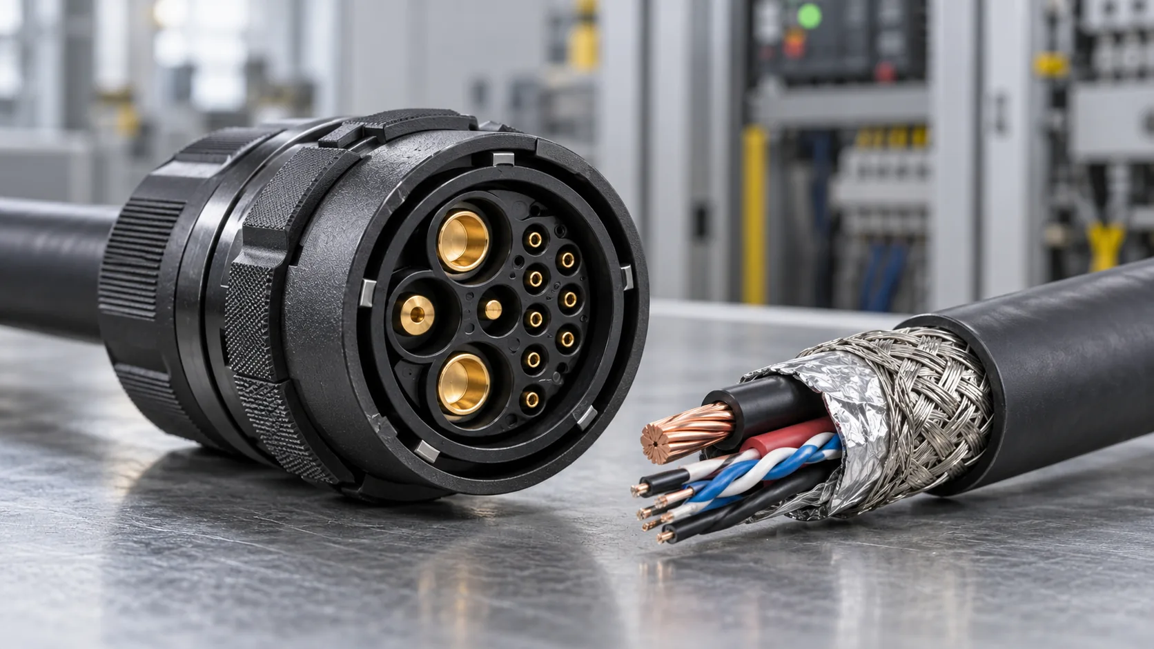
For a modular cable splitter, the connection matrix is the central acceptance document. Label the trunk connector and every branch with unique identifiers. Record connector part numbers, mating parts, contact gender, keying, cavity numbers and conductor identifiers. Show whether pin numbers are viewed from the mating face or wiring side. Mirrored views are a common source of apparently reasonable but incorrect wiring.
List every permitted connection and every required isolation. A simple one-to-two power split might share a supply conductor and return, but a sensor harness may route separate outputs through different trunk contacts. Do not join independent push-pull sensor outputs merely because their wire colors match. Protective earth, functional earth, shields and signal returns need deliberately defined treatment. They should not be merged by a factory operator's interpretation.
| Drawing item | What to specify | Verification |
|---|---|---|
| Trunk and branch ports | Unique connector and cavity IDs | Check against mating-face drawings |
| Shared conductors | Explicit junction points and wire sizes | Continuity to every intended destination |
| Separate circuits | Forbidden connections and shield scheme | Isolation test using the approved method |
| Branch identification | Durable labels and orientation | Visual comparison with installation drawing |
Keep revision control on both the circuit map and mechanical drawing. The cable assembly pinout and intermittent-fault checklist provides a complementary testing framework for checking an assembled harness against that map.
Calculate Trunk Current and Branch Loads Separately
A branch connector's current rating is not permission to multiply that current by the number of outlets. For a simple DC distribution network, a shared supply conductor carries the sum of the branch currents flowing through it. The corresponding shared return must also be assessed. In a daisy-chain arrangement, the upstream segments may carry more current than the final segment, so one rating cannot be applied blindly to the whole route.
As an illustrative calculation, two loads drawing 3 A simultaneously require 6 A through their common supply path, excluding other loads and transient behavior. This is arithmetic for a hypothetical circuit, not a JNICON product rating. It does not establish the necessary wire size, connector rating or protective-device setting. Those decisions depend on temperature, duty cycle, installation, insulation, contact loading and the complete component specifications.
Prepare a load schedule with steady current, start-up current, duration, repetition and expected simultaneous operation. If diversity is used, explain how the control system enforces it and what happens during a fault or restart. Evaluate the weakest element of each path: contact, crimp, splice, conductor, junction and mating interface. Include future expansion only as a documented allowance, not an unverified promise that unused outlets provide spare capacity.
For circuits with different phases, sources or return arrangements, use the correct circuit analysis rather than simply adding nameplate numbers. Never parallel supply outputs or connector contacts unless the equipment design and manufacturer explicitly support that arrangement.
Budget Voltage Drop Along the Complete Supply and Return
Voltage measured at the power supply is not necessarily the voltage available at the load. The trunk, branch conductors and connection points all contribute resistance. For a steady DC path, the basic relationship is voltage drop equals current multiplied by resistance. Use the complete supply-and-return loop. A shared trunk's drop depends on the total current through that trunk, while each branch contributes its own additional drop.
For example, an assumed trunk loop resistance of 0.10 ohm carrying 6 A produces a 0.60 V drop. An assumed branch loop resistance of 0.15 ohm carrying 3 A adds 0.45 V, giving 1.05 V along that load's route before other unmodeled losses. These invented values demonstrate the method only. Replace them with measured or justified design values and the actual load's minimum operating voltage.
Check the remote branch at the least favorable supply setting, cable temperature and simultaneous load condition. Start-up events may create a larger temporary drop than normal running. Record both the load-terminal voltage and supply-terminal voltage so a weak source is not confused with harness resistance. If an intermittent reset occurs, compare it with switching events on the other branch. Correct pinout alone does not guarantee an adequate voltage margin.
Coordinate Protection with Each Branch and the Shared Feed
A passive T/Y junction does not become a protective device because it is enclosed or overmolded. A shared upstream fuse may be appropriate in some equipment designs, but it must be checked against every downstream conductor and component it protects. A small branch wire may not tolerate the same fault energy as a larger trunk. Protective-device selection and coordination belong to the equipment's electrical design, not to an assumed splitter feature.
Define what a short circuit, overload, reverse connection or loss of return should do. Determine whether one failed branch may shut down the whole machine, or whether separate branch protection is required. Specify the location and accessibility of protective devices and how a technician identifies the affected circuit. Do not assume that a power supply's current limit provides all necessary branch protection under every fault condition.
Manufacturer documentation illustrates why the distinction matters: passive distribution products and fieldbus distributors with explicitly integrated current limitation are described as different configurations. Those references are general engineering context, not evidence that a JNICON harness contains current-limiting electronics. Require the supplied assembly's own schematic and component list.
Do Not Treat a Signal Splitter as a Universal Data Hub
Power distribution and signal distribution need different reviews. A passive wiring junction can route discrete sensor circuits according to a defined map, but it does not automatically regenerate a signal, manage network traffic or convert protocols. An encoder splitter module may need buffering or isolation. A pulse splitter module may need defined input thresholds and output drive capability. Those functions cannot be assumed from a cable assembly's name.
For a communication circuit, identify the exact protocol, data rate, cable construction, allowed topology, termination and length limits. A branch can introduce a stub and alter impedance. Conventional point-to-point Ethernet connections are not turned into a working network by joining conductors in a Y cable. Use a protocol-approved architecture and the required active equipment rather than assuming a power splitter's topology also suits data.
Keep power returns, shields and differential pairs under drawing control. Preserve pair geometry through the interface where required, and assess noise when high-current loads switch. The existing hybrid connector power-and-signal EMI guide explains complementary checks. If the supplier cannot document the proposed signal function, keep the application outside the approved scope until the correct interface design and validation are available.
Validate Sealing, Cable Support and Unused Ports
A T splitter cable assembly adds a junction and potentially more service interfaces. Review the environmental exposure at each one: rain, spray, temporary immersion, condensation, dust, oils or cleaning agents. An IP claim applies to a defined assembly and condition. Ask whether the stated performance requires fully mated connectors, a particular cable diameter, specified tightening and matching caps on unused ports.
Overmolding can protect a junction, but the material, cable jacket and molding process must suit the application. Check jacket compatibility and the transition between rigid molding and flexible cable. Do not put a clamp directly on a flex transition or use the junction as a handle to pull the harness into place. Route and support the branches so their weight and vibration do not continually load the connector contacts or seals.
Assess disconnected maintenance conditions separately from normal operation. A dust cover is not necessarily a qualified sealing cap. Unused outlets may need a specific cap, mounting orientation or protected location. If moisture symptoms appear despite an apparently intact seal, distinguish external leakage from internal condensation before replacing parts. Document environmental and mechanical conditions alongside the electrical requirements so the supplier can review one complete installation.
Test the Splitter Assembly Under Representative Combined Loads
Begin verification with an unpowered inspection and a complete connection-matrix test. Confirm port labels, polarity, intended connections and required isolation before applying power. Use approved test equipment and procedures appropriate to the assembly. Insulation or dielectric testing must use specified conditions and must not be applied through attached electronics that are incompatible with that test.
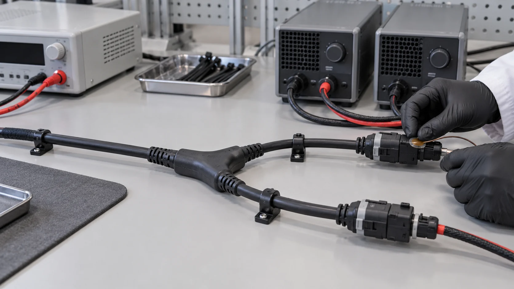
Then evaluate representative combinations of branch loads, not only one outlet at a time. Include the highest justified simultaneous load, an uneven-load case and relevant start-up events. Measure source voltage, remote load voltage and temperatures at defined locations. Record ambient conditions, stabilization criteria, cable arrangement and measurement equipment. Compare results with documented component and application limits rather than inventing a universal acceptable temperature.
After the applicable environmental or mechanical exposure, repeat the agreed electrical checks. A functional check immediately after assembly does not demonstrate performance after vibration, bending or water exposure. Investigate drift, intermittent opens, local heating or changed connector retention before release. Deliberate fault testing must be designed and carried out by qualified personnel using suitable protection and a controlled test setup.
Make Production and Replacement Assemblies Traceable
A successful prototype should lead to a controlled production definition. Release the bill of materials, contact and cable specifications, approved mating components, branch lengths, labels and pin map together. Record which properties are verified on every assembly and which require sampled or qualification testing. A statement that a harness was tested is not enough if the test coverage cannot be matched to the released drawing.
Keep a traceable record of the harness revision, manufacturing lot and test result. The operator should use a controlled fixture that checks all intended paths and detects unintended cross-connections. Visual inspection should cover connector locking features, seals, molding defects, cable damage and label placement. Define a process for quarantining failed assemblies and retesting authorized repairs. Avoid treating a repaired sample as equivalent to the original process without review.
Replacement planning also matters. Provide service teams with an exact assembly identifier and approved mating information. A physically compatible substitute may have different pin assignments or cable properties. Changes to resin, plating, wire supplier, splice construction or connector family should trigger an engineering review of the affected requirements. Keep the validation record linked to the configuration actually delivered.
Send a Complete Splitter Module RFQ to the Manufacturer
A useful request for quotation lets engineering and purchasing compare the same scope. Send the connection matrix and installation layout before requesting a final price. Identify the application, operating voltage, branch and trunk load profiles, cable lengths, environmental exposure and service expectations. Include annual demand and sample quantities as planning inputs without assuming a fixed lead time or minimum order quantity.
- Connector and mating-part references, contact gender, keying and pin-view convention.
- Trunk and branch conductor sizes, cable construction, labels and dimensional datums.
- Required shared circuits, isolated circuits, shield treatment and any protection supplied separately.
- Combined-load, mechanical and environmental acceptance requirements with report expectations.
- Inspection coverage, traceability, packaging, change control and replacement requirements.
Ask the supplier to mark unresolved items instead of silently choosing defaults. A drawing-based review can reveal that a simple molded junction is sufficient, or that a protected distribution device, active signal module or different network architecture is necessary. JNICON's custom harness and connector range can support that discussion, but the final design must be assessed against the exact application. Do not transfer ratings from an unrelated catalog model to a new multi-branch assembly.
Related Products for OEM Branch Harnesses
These catalog products are starting points for a drawing-based review, not a pre-approved splitter combination. Confirm exact mating parts, cable construction and application ratings.

Custom OEM Wiring Harness & Cable Assembly for Medical & Industrial Equipment
We provide fully customized wiring harness & cable assembly services, covering twisted pair wires, flat ribbon cables, double-ended terminal cables, multi-core sheathed wires, USB conversion harnesses, multi-branch loom wiring, O-type ground lug cables and customized plug connection lines. Widely applied in medical instruments, industrial automation, intelligent equipment, printing devices, motor drive systems and electronic control modules, support drawing & sample personalized OEM & ODM production.

M12 2 Pin Waterproof Connector 7A Push Locking Molded with Cable for Sensors & Automation
7A 2-pin push-locking waterproof connector pre-molded with cable, IP67-rated for ready-to-use sensor and industrial automation connections.
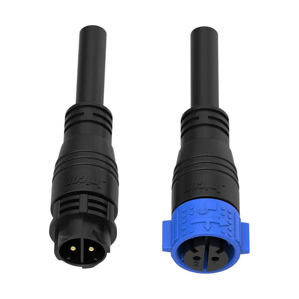
M25 2-Pin Waterproof Connector 50A Push Locking Molded with Cable for Solar & Energy Storage
Pre-molded 50A push-locking waterproof connector with IP67-rated cable, ready-to-use for reliable outdoor power connections in solar and energy storage systems.
Related Industrial Solutions
Review branch layouts against the actual equipment, loading and maintenance requirements in these application areas.

Industrial Automation
Power, signal, and data connectivity for factory machines, robotic cells, sensors, and control cabinets. JNICON can review circular connectors and cable assemblies against motion, sealing, shielding, and maintenance requirements before prototype approval.
Explore Solutions
Outdoor Lighting & LED
Power and control connections for outdoor luminaires, architectural lighting and LED installations. JNICON can review connectorized cables, locking styles and sealing arrangements against driver loads, cable dimensions, weather exposure and maintenance needs.
Explore Solutions
Security & Safety
Power and signal connectivity for surveillance, alarm, access-control and outdoor security equipment. JNICON can review circular connectors, Ethernet interfaces and cable assemblies against the installation drawing, data requirements and exposure conditions.
Explore SolutionsFAQ: Splitter Module and Branch Harness Design
Conclusion: Approve the Complete Branch Circuit
A reliable splitter module starts with a controlled circuit map and ends with evidence from the complete assembly. Choose the T or Y geometry for installation, size the shared feed for the real combined load, verify voltage at the remote equipment and coordinate branch protection. Keep signal-network requirements separate from simple power distribution. Sealing and strain relief must match the connected and maintenance states, not only the catalog illustration.
Before ordering production quantities, resolve open drawing items and agree on the tests that prove the intended function. Send JNICON your splitter harness drawing and load schedule to request a configuration review and quotation. Include both normal operation and foreseeable service conditions so the proposed assembly can be evaluated against your actual OEM equipment.