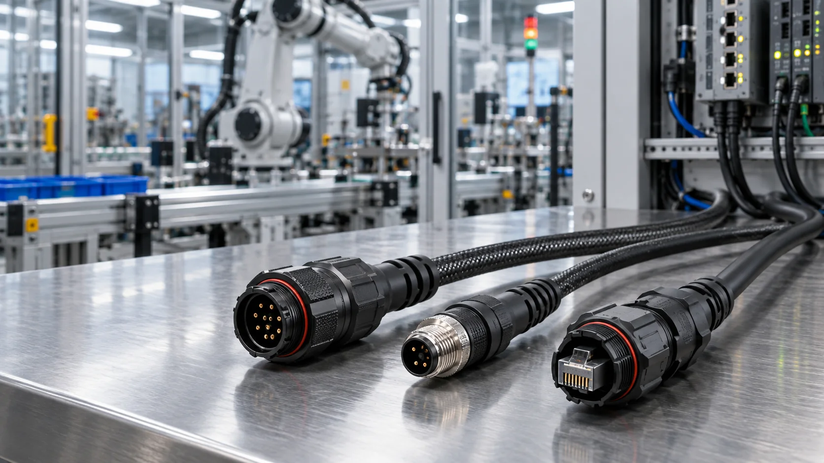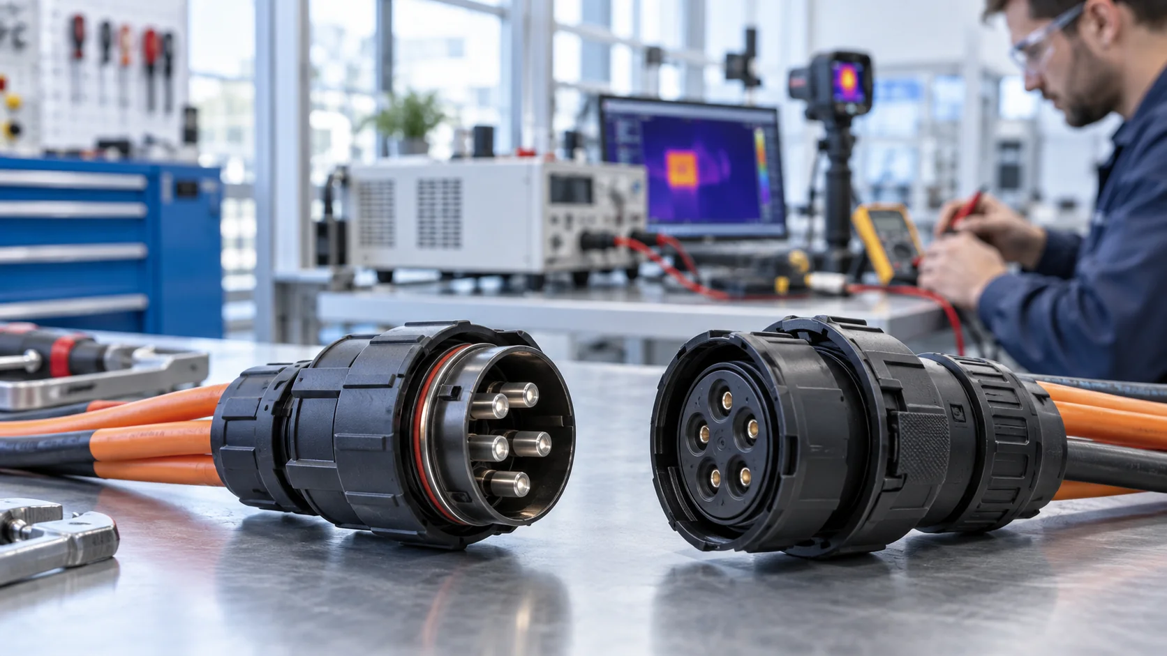
Hybrid connectors can combine power and signal connections in one interface, but fewer plugs do not automatically mean fewer faults. For factory OEMs, the real task is to keep communications stable while motors, contactors, and switching power supplies operate. This guide explains how to review pin assignments, shielding, cable routing, and test evidence before approving a hybrid cable assembly for production.
What Hybrid Connectors Can—and Cannot—Solve
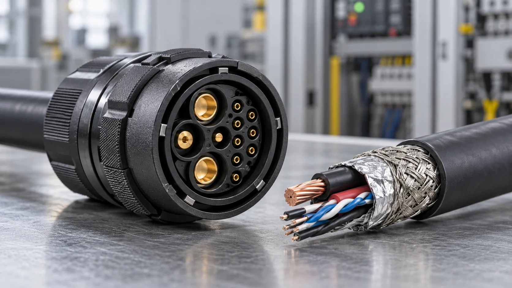
A hybrid connector houses different electrical circuits within one mating interface. Larger contacts may carry power while smaller contacts carry control, feedback, or auxiliary circuits. The arrangement can simplify machine installation and reduce the number of separate cable connections. It also concentrates electrical, mechanical, and service requirements into a single assembly.
The key purchasing distinction is between contact capacity and communication performance. A catalog may identify current, voltage, contact count, locking method, and an ingress rating. Those details do not, by themselves, establish compatibility with Ethernet, CAN, an encoder, or a precision analog input. A small contact described as a signal contact is not proof of controlled impedance, sufficient bandwidth, or effective shielding.
For power and hybrid connectors, start with the circuit requirements and then assess the complete installed path. Include the cable, terminations, enclosure entry, PCB interface, and grounding arrangement. A connector that suits low-speed status inputs may need additional evaluation for high-speed differential communication.
JNICON offers mixed-contact connector configurations for industrial power and signal applications. Its hybrid connector selection guide covers the broader selection process. This article focuses on interference risks and the evidence an OEM should request. Treat every recommendation as a design-review checkpoint, not as a claim that a particular product has passed your machine-level EMC requirements.
Recognize the Difference Between EMI and Other Faults
Electromagnetic interference can disturb a signal even when every conductor passes a continuity test. Typical symptoms include communication retries during acceleration, encoder errors when a drive switches, analog readings that jump when a contactor closes, or intermittent controller resets. These observations identify a useful trigger. They do not prove that the connector is the cause.
Separate interference from voltage drop, a loose terminal, incorrect software configuration, moisture ingress, or mechanical damage. Log the operating event, the affected channel, supply voltage at the receiving device, and the controller error. Compare a repeatable baseline with the suspect condition before replacing components.
Build a symptom-to-test record
- Errors during motor acceleration: compare communications while recording drive activity and receiver supply stability.
- Faults after cabinet maintenance: inspect shield bonds, connector seating, cable routing, and changed ground connections.
- Failures after warm-up: investigate contact resistance, voltage drop, temperature, and electronic limits alongside EMI.
- Errors only with a longer cable: evaluate protocol length limits, termination, attenuation, and routing exposure.
One-variable comparisons are particularly valuable. Change routing while keeping the connector and cable unchanged, or compare two approved assemblies in the same fixture. If several variables change together, the result may improve without explaining why. Preserve failing samples and their build records so that engineering and the supplier can review the same evidence.
Define Circuits Before Choosing a Hybrid Cable Connector
Before selecting a hybrid cable connector, create a circuit matrix. List operating voltage, continuous current, transient behavior, conductor size, protocol, cable length, and the return path for each circuit. Separate protective earth, chassis bonding, signal reference, and power return. They may connect within an engineered grounding design, but they are not interchangeable labels.
Ask whether the power circuit is a steady DC supply, a switched load, or a drive output. The interference environment can differ substantially. For signal circuits, identify the actual interface rather than writing only “data.” A CAN bus, an incremental encoder, an Ethernet link, and a thermocouple input need different cable and termination decisions.
Document the permitted operating states. For example, an assembly might power a remote module while carrying sensor feedback, yet need to withstand the noise created by a neighboring inverter. The specification should capture that installed environment, not simply the connector’s location on a clean drawing.
Include connection and disconnection rules. Do not assume that a mixed-contact connector supports live mating, a protective-earth sequence, or an interlock. Require product-specific confirmation where those functions are needed. Review safe shutdown and stored energy with the machine’s electrical designer.
For the cable itself, JNICON’s industrial data cable selection guide provides a complementary review. Specify the complete assembly and revision so that procurement does not replace an approved cable with a visually similar alternative.
Review Pin Layout, Pair Geometry, and Physical Separation
Pin count alone is a weak comparison between high density hybrid connectors. Review the mating-face drawing, contact sizes, polarity, keying, and the assignment of every circuit. Establish whether the drawing shows the mating face or the termination side. A mirrored interpretation can produce a serious wiring error even when the contact numbers appear familiar.
Preserve the intended relationship between differential conductors through the assembly. Avoid splitting a pair across distant contacts without evaluating the resulting geometry. Keep untwisted lengths controlled at the termination and record the approved arrangement in a drawing or work instruction. Short, consistent transitions are preferable to uncontrolled loops.
Assess physical separation between noise-producing circuits and sensitive channels. There is no universal spacing value that guarantees immunity across all voltages, frequencies, and connector designs. The required insulation coordination and the required signal performance are separate design questions. Obtain suitable product information and validate both.
A useful sample review includes photographs of the termination area, conductor identification, shield handling, and strain relief. Check that production can reproduce the approved build without relying on the memory of one technician. Where the termination is hidden by molding, agree on pre-mold inspection evidence or representative sectioned samples.
The objective is a controlled transition from cable to connector, not simply a neat-looking exterior. A compact assembly may save installation space while still requiring careful pair geometry and a qualified shielding path.
Check the Shield Path Across the Whole Installation
A shield works as part of an installed electrical path. Review how the cable screen reaches the connector, whether the connector provides an intended conductive path, how the panel interface bonds to the enclosure, and what happens at the receiving electronics. Do not infer shielding performance from a metal appearance or from the word “waterproof.”
At high frequencies, bond geometry matters as well as DC resistance. An extended drain-wire connection can behave differently from a short circumferential screen termination. Where the design calls for a surrounding shield connection, verify that the selected backshell, cable diameter, and termination method actually provide it. Do not improvise a screen bond onto an unspecified housing.
The grounding strategy must be decided for the system. Connecting a screen at one end, both ends, or through an engineered network has different implications for frequency response and potential differences. Avoid universal rules such as “always disconnect one end.” Consult the equipment grounding design, interface documentation, and applicable safety requirements.
Record the shield termination as a controlled assembly feature: screen preparation length, clamp location, contact surfaces, cable compatibility, and inspection criteria. Paint, corrosion, an incorrect gasket, or an insulating panel arrangement may interrupt a bond that looked correct on the bench.
Inspect the final installed state after servicing as well as the original sample. An assembly that passes before a cabinet panel is removed should not depend on an undocumented bond that maintenance can accidentally omit.
Route Power and Signal Cables for the Real Machine
Once power and signal share an interface, cable routing becomes especially important. Evaluate proximity to drives, switching supplies, motor cables, contactors, and other repeatable noise sources. Keep sensitive paths away from these sources where the machine layout allows, and control unavoidable crossings and parallel runs.
Do not specify a universal separation distance without knowing the cables, shielding, installation, and noise environment. Instead, capture the approved routing in a machine drawing and test the most exposed practical configuration. A successful test with a short, loosely arranged bench cable may say little about a tightly bundled installation.
Check bend radius, clamping, service loops, and movement. Mechanical requirements can force a screen or pair geometry to change near the connector. Repeated flexing can also create an intermittent defect that resembles interference. Review both mechanisms rather than assuming every random communications error is electrical noise.
During troubleshooting, temporarily separating a suspect signal path from a drive cable can be informative. If errors stop, document the comparison and investigate coupling. The temporary arrangement is not automatically an acceptable production solution; it still needs mechanical protection and repeatable installation.
Route the assembly so that technicians can mate, lock, and inspect it without twisting the cable or pulling on the termination. A service-friendly layout reduces the chance that a correctly engineered hybrid connector will be reinstalled incorrectly after a component replacement.
Run a Controlled Power-and-Signal Test Matrix
Start with a defined assembly revision and a repeatable fixture. Record connector variants, cable construction and length, pin assignments, screen bonds, supply conditions, receiver hardware, firmware, traffic rate, and the physical routing. Capture photographs so another engineer can reproduce the setup.
Establish a quiet baseline and then introduce realistic operating conditions. Exercise the actual loads rather than assuming that a laboratory supply recreates a motor or switching converter. Keep the power circuit within the approved electrical limits and use appropriately rated instruments, isolation, and qualified personnel.
| Test condition | What to record | Why it matters |
|---|---|---|
| Quiet baseline | Error counters, signal quality, supply stability | Separates pre-existing faults from load-related effects |
| Steady representative load | Current, temperature, voltage drop, communication errors | Checks the sustained operating state |
| Repeated load transitions | Event timing, retries, resets, analog deviation | Exposes disturbances during switching |
| Longest approved cable and exposed routing | Same metrics plus routing photographs | Tests the installation boundary |
| After agreed mechanical conditioning | Bond continuity, contact condition, repeated functional results | Checks whether performance remains stable |
Define observation time and pass criteria before running the test. “No visible problem” is not an adequate acceptance statement if software hides retries or automatically reconnects. Log the counters and recovery behavior that affect your machine.
Formal EMC testing is a separate activity. Have the responsible compliance engineer or laboratory define applicable standards, severity levels, operating modes, and performance criteria for the final equipment. An internal checklist cannot replace that assessment.
For example, a remote actuator may communicate correctly while idle but lose feedback during repeated start-stop cycles. A useful comparison holds the actuator, software, cable length, and receiver constant while changing only the approved routing or assembly under investigation. Repeat the same operating sequence and retain the timestamped logs. This is a hypothetical troubleshooting example, not a reported JNICON customer result. If the change appears effective, run the agreed boundary conditions again before deciding that the problem is resolved. An improvement in one short test is a reason for further validation, not a complete production release.

Measure Communication Performance with Protocol-Specific Criteria
Use measurements appropriate to the interface. For CAN, review termination and network topology alongside error counters. For Ethernet, assess the link, cable channel, and implementation requirements for the intended data rate. For analog signals, record accuracy, repeatability, and transient deviation against the measurement budget.
Texas Instruments explains that imbalance in differential CAN signals can create common-mode disturbances and that termination design can influence EMC behavior. See its CAN termination and EMC technical article. This illustrates why connector selection, cabling, and electronics must be reviewed together. It does not certify any JNICON assembly or prescribe one termination circuit for every network.
Choose instrument connections carefully. An unsuitable probe or added ground path can alter the circuit being measured. Preserve the normal installation and document unavoidable changes to the fixture. Compare results using the same measurement method and the same hardware revision.
Pass criteria should connect to the application: permitted data errors, recovery time, missed motion events, control accuracy, or safety-related behavior. Do not use an arbitrary universal bit-error threshold merely because it looks precise. The interface and system requirements determine the acceptance limit.
Store raw logs as well as the summary. A supplier can make a more useful recommendation when the report identifies the failed channel and operating event instead of stating only that the connector “has EMI.”
Keep Thermal, Sealing, and EMC Evidence Separate
An ingress rating addresses specified environmental tests. It does not establish electromagnetic immunity. Likewise, a successful communications test at room temperature does not establish current capability at the maximum installed ambient temperature. Keep those evidence categories separate in the approval record.
Review temperature rise with the actual loading pattern and cable size. Adjacent loaded contacts, enclosure conditions, and cable bundling can affect the assembly. Use the relevant product limits and agreed test conditions rather than transferring a headline current rating to every pin simultaneously.
Contact heating can create supply instability or long-term deterioration that complicates an EMI investigation. JNICON’s high-current connector overheating checklist explains the complementary thermal review. If a fault appears only after warm-up, evaluate the power path and electronics before redesigning the shield.
Check seals, cable entries, and coupling instructions for the selected configuration. A different cable diameter or accessory can change the environmental performance. Do not claim that an IP rating covers an unmated connector, pressure washing, or chemical exposure unless the specific documentation supports it.
A release decision should therefore reference multiple records: electrical safety, current and thermal performance, mechanical retention, environmental suitability, functional communications, and equipment-level EMC. A failure in one category is not cancelled by a pass in another.
Specify Supplier Evidence and Production Controls
When requesting quotations for hybrid connectors, send a requirement package rather than only a photograph. Include the circuit matrix, mating-face pinout, cable specification, installed route, expected loads, communication interface, environment, quantities, and desired sample evidence.
Ask the supplier to identify what is confirmed by a catalog, what needs a drawing review, and what remains subject to sample or system testing. Useful evidence includes the approved assembly drawing, material and component identification, inspection records, applicable product reports, and traceability to the tested revision. Request documents for the specific model; do not treat a company-level certificate as a report for every assembly.
Control the features that affect repeatability
- Connector and cable part numbers, approved equivalents, and revision identifiers.
- Pin assignments, pair identification, termination process, and polarity checks.
- Screen preparation, bond method, strain relief, and cable entry configuration.
- Specified continuity, insulation, and functional checks with appropriate test limits.
- Rules for changes to materials, tooling, cable length, or assembly instructions.
JNICON’s listed M19, M23, and M40 mixed-contact families provide starting points for a technical discussion. Choose among them using actual circuit and installation requirements, not shell size alone. Any claim of protocol performance or EMC conformity should be supported by evidence for the intended assembly and equipment.
Before volume release, retain an approved sample and the test configuration. Define how the OEM and supplier will assess substitutions. A small change to a cable screen, contact assignment, or termination length can matter even if the exterior remains identical.
Related Products for Power-and-Signal Reviews
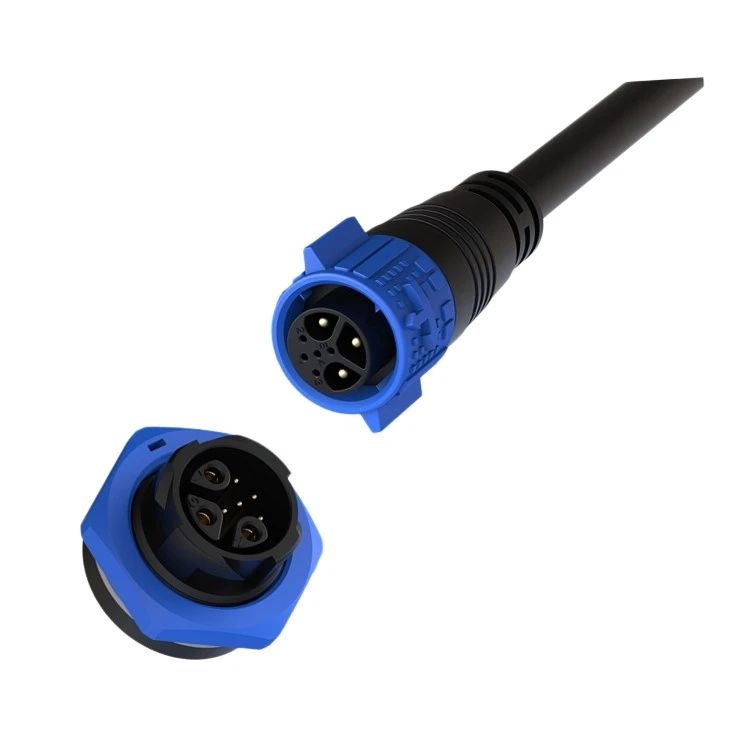
M19 3+5 Pin Hybrid Waterproof Connector 15A+5A Push Locking IP67 for Power & Signal
15A+5A hybrid push-locking waterproof connector combining power and multi-signal in one M19 housing for industrial control systems.
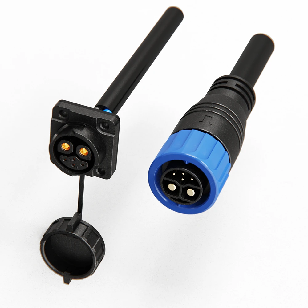
M23 6-Pin Hybrid Waterproof Connector 50A+5A Push Locking for Power & Signal
50A+5A hybrid push-locking waterproof connector with IP67 rating, combining power and signal transmission for industrial automation and energy systems.
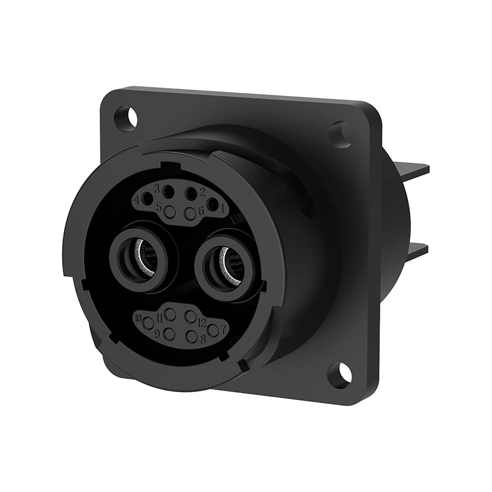
M40 2+4 Pin Hybrid Waterproof Connector for Power and Signal
120A+10A hybrid bayonet lock waterproof connector combining power and signal in one compact design.
Related Industrial Solutions

Industrial Automation
Empowering smart factory infrastructures with certified power, signal, and data connectors. Engineered to withstand continuous multi-axis robotic motion, eliminate electromagnetic interference (EMI), and ensure zero-downtime performance in harsh manufacturing environments.
Explore Solutions
New Energy & Energy Storage
Safeguarding high-capacity grid infrastructures with certified high current connectors engineered to withstand massive voltage loads, minimize thermal buildup, and eliminate systemic arcing risks from cell to grid container.
Explore Solutions
Rail Transit
Empowering rolling stock, trackside signaling networks, and passenger information systems with certified heavy-duty power and signal connectors. Engineered to endure continuous dynamic vibrations, violent mechanical shocks, and extreme outdoor weathering.
Explore SolutionsFAQ: Hybrid Connector EMI Reviews
Conclusion: Approve the Complete Power-and-Signal Path
Reliable hybrid connectors depend on a controlled assembly and installation: suitable contacts, defined pin assignments, consistent pair geometry, an engineered shield path, practical routing, and evidence from representative operating conditions. Combining circuits is valuable when it reduces assembly complexity without obscuring the requirements of each interface.
Use this checklist to turn a broad request for “power plus data” into a reviewable specification. Identify the operating events most likely to cause faults, define acceptance criteria before testing, and keep functional, thermal, environmental, and compliance records distinct.
For a JNICON project review, share your pinout, current and voltage requirements, signal protocol, cable length, installation photographs, and target environment through the JNICON inquiry and contact page. Request a suitable connector-and-cable configuration and agree on the sample evidence needed before production approval.