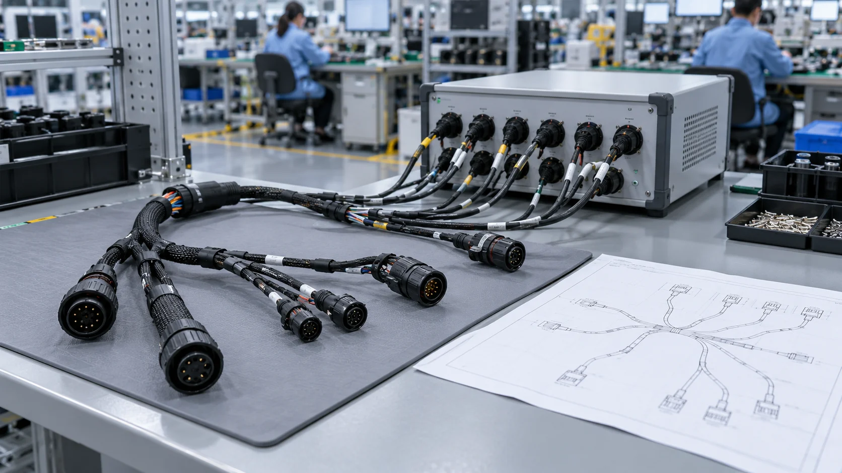
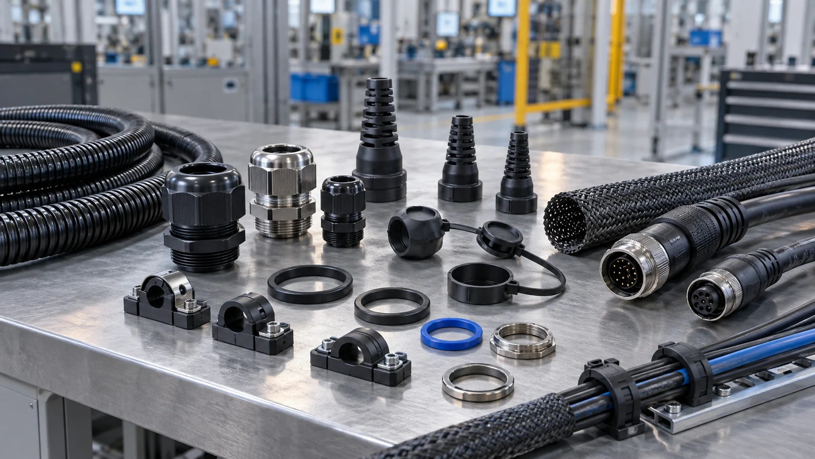
Custom cable assemblies for moving equipment need more than a correct pinout. Use this OEM guide to define bend radius, motion, flex-life acceptance and inspection evidence before approving a cable assembly for production.
A cable that works on a stationary bench may fail when a carriage reverses, a service loop tightens or a robot twists its routing. This guide addresses motion qualification, rather than general supplier selection or a basic end-of-line continuity check. It provides a planning checklist, not a universal cycle rating, a certification claim or a substitute for your machine-specific engineering assessment.
Define the Motion Before Specifying Flex Life
Start with the path that the assembly follows, not an arbitrary number of bends. Record the moving and fixed endpoints, usable space, travel distance, orientation, speed, acceleration and dwell. Photograph or sketch the assembly at both travel limits and at any position where the cable changes direction. Include start-up, normal production, homing, jam recovery and maintenance movements.
Separate rolling flex in a cable carrier from repeated bending at one point, free hanging movement and torsion around the cable axis. These conditions do not load the cable in the same way. A route combining bending and twisting requires evidence for that combined motion; a rolling-flex result alone does not establish suitability.
Define one cycle in writing. For example, a complete outward-and-return movement may count as one cycle in your protocol, whereas another report may count each stroke separately. State the counting convention before comparing results. Translate the machine's intended service interval into motion demand using documented operating assumptions, including productive hours, movements per hour and maintenance policy. Keep occasional service movements separate from production cycles.
Custom cable assembly manufacturers can review a clear motion specification more effectively than a request that only says flexible cable. If the machine route is still changing, identify that uncertainty and qualify the final installed geometry before release.
Distinguish Static, Dynamic and Torsional Requirements
A static minimum bend radius describes a fixed installation condition. Do not automatically apply it to repeated movement. The selected cable's current datasheet should identify whether it supports continuous flexing, occasional movement, torsion or only stationary use. Check the conditions and limitations, not just an adjective such as flexible.
For a concrete example of why the distinction matters, LAPP's published ÖLFLEX ROBUST FD 4G2.5 product data lists different static and dynamic bend-radius limits and separately states its torsional suitability. Those values belong to that particular cable; they are not a JNICON assembly specification.
For your own design, obtain the actual cable part number, revision and outer diameter, then document the applicable radius and motion category. Confirm whether the radius is referenced to the inside curve, centerline or another datum in the manufacturer's instructions. Measure the installed route using the same convention. Avoid comparing a diameter with a radius or substituting a nominal chain dimension for a verified cable path.
A larger carrier radius does not resolve every problem: the cable may still be twisted during installation, crowded by adjacent hoses or sharply bent at an exit. Review the whole path, including terminal transitions. If the manufacturer does not provide appropriate dynamic evidence, treat suitability as unconfirmed rather than assigning a generic multiplier.
Freeze the Complete Cable Assembly Configuration
Qualify a defined assembly, not an undefined family of parts. Freeze the drawing revision, bill of materials, conductor sizes and counts, shielding construction, cable length, connector orientation, terminations, backshells, overmold geometry and strain-relief dimensions. Identify the flexible zone and the sections intended to remain fixed.
Make the sample representative of the production process. A hand-built prototype with different tooling, jacket preparation or a longer free tail can move differently from the production article. Label every sample and record its manufacturing lot, cable batch and any deviations from the released drawing. Keep a retained uncycled reference when useful for comparing jacket condition and dimensions.
The weakest transition may be near the connector, a branch, a tie point or a change in stiffness rather than at the middle of the moving span. An overmold can provide support but can also relocate bending into a shorter adjacent section. A cable-level lifetime claim therefore should not be treated as automatic approval of the finished assembly.
When evaluating custom cable assembly solutions, request evidence that matches both the chosen cable and the termination design. Material substitutions, altered shield termination, different branch positions or revised molding deserve change-control review. Decide in advance which changes require a drawing update, a targeted retest or full motion requalification.
Build a Representative Flex Test Fixture
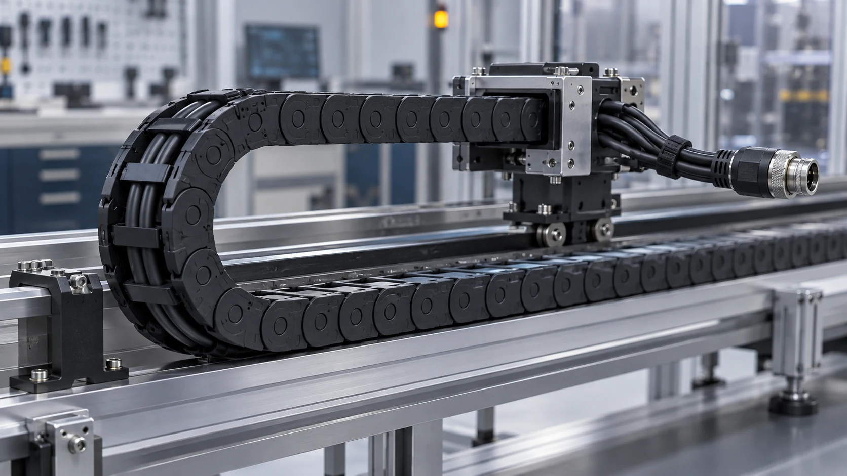
The fixture should reproduce the important geometry and constraints of the installed machine. Record the carrier type, bend radius, support method, cable arrangement, separators, exit alignment and clamp positions. Check that the cable is installed according to the relevant cable and carrier instructions, without introducing an unintended twist.
Keep connectors and terminations in their intended fixed or moving positions. Do not allow a laboratory clamp to support a transition that remains unsupported in the real installation. Conversely, do not create a sharp artificial bend solely because the test bed is small. If a reduced-size fixture is necessary, document which stresses it reproduces and which it cannot represent.
As an application-specific testing example, igus describes its cable-testing approach using carrier motion and separate torsion testing rather than assuming a roller-bending result reproduces every installed condition. This is manufacturer-specific methodology, not evidence that another assembly has passed those tests.
Before the endurance run, perform slow commissioning movements and inspect both travel extremes. Look for rubbing, stacking, snagging, migration, connector rotation and clamp movement. Record a short baseline video and fixture photographs. Correct setup errors before counting qualification cycles, then lock the configuration so later results remain comparable.
Set Acceptance Criteria Before Running the Test
Agree on a test plan before specimens enter the fixture. State the purpose: screening concepts, qualifying a released design, comparing alternatives or investigating a field failure. Each purpose needs a suitable sample plan and decision rule. A successful demonstration on one sample is not a statistical reliability guarantee.
| Protocol item | What to record | Acceptance decision |
|---|---|---|
| Identity | Assembly revision, materials, lot and sample IDs | Samples match the approved configuration |
| Motion | Cycle definition, travel, radius, speed and acceleration | Conditions match the agreed application envelope |
| Electrical function | Circuits monitored, thresholds and event duration | No event outside the agreed limits |
| Mechanical condition | Jacket, clamps, branches and terminations | No unacceptable damage or displacement |
| Evidence | Checkpoints, raw logs, deviations and final examination | Traceable evidence supports the release decision |
Define permissible resistance change, transient interruption criteria and visible-damage limits with the responsible engineers. Select thresholds and sampling capability appropriate to the connected equipment. Do not copy an unexplained numerical limit from a different cable, voltage class or communications interface.
Specify what happens after an interruption or fault: immediate stop, controlled examination or a separate investigation. Preserve the original event log. Repairing a sample and restarting does not erase its failure; distinguish the original test from any subsequent diagnostic run. Record planned pauses separately from unplanned stoppages so the total cycle count is not misleading.
Monitor Intermittent Faults During Movement
A continuity check performed only after the cable returns to rest can miss a conductor that opens at one travel position and reconnects elsewhere. Plan monitoring during motion when intermittent faults matter to the application. Map each measured channel to the approved pinout and identify any circuit that is not monitored.
The monitoring system must be able to capture the event you intend to detect. Document sampling rate, event-duration threshold, electrical stimulus, connection method and instrument limitations. A slow status lamp or occasional meter reading should not be presented as proof that short interruptions did not occur. Validate the detection setup with a controlled test condition before relying on its logs.
For power circuits, consider resistance trends and thermal behavior under the separately approved loading conditions. For communications circuits, use interface-appropriate functional checks: stable DC continuity alone does not demonstrate acceptable data transmission. Protect instruments and fixtures from inappropriate voltage or current, and perform energized testing only under a reviewed laboratory procedure.
Use cycle count, time and carriage position together to investigate events. Repeated faults near the same reversal can point to a route or transition issue, but diagnosis still requires examination. For a complementary wiring check, see the cable assembly pinout and intermittent-fault testing guide. Flex qualification adds motion evidence; it does not replace correct wiring verification.
Inspect the Jacket, Shield and Strain-Relief Transitions
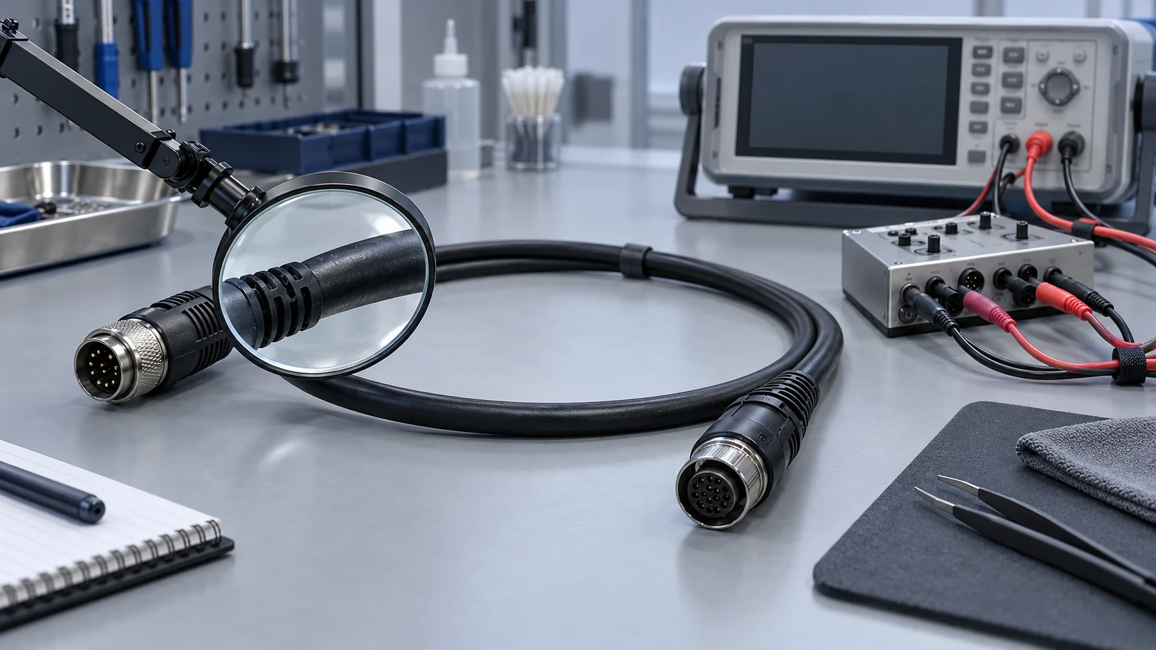
Schedule inspections at agreed checkpoints, not only at the end. Photograph the same locations and orientations so progression is visible. Examine the outside curve, cable exits, branch transitions, clamp contact areas and connector entry. Record changes without disturbing the setup more than the protocol permits.
Look for abrasion, cracks, flattening, jacket migration, bulging, loss of support and movement of the connector or clamp. A clean exterior does not establish that internal strands, insulation or shielding are intact. Conversely, a superficial mark needs an agreed classification rather than an automatic pass or failure based on appearance alone.
Measure selected dimensions and electrical characteristics against the baseline using a repeatable method. Where the test plan requires destructive examination, identify the specimen and section location, photograph the exposed construction and distinguish damage introduced during disassembly from damage caused by testing. Preserve representative failed parts for root-cause review.
A custom cable assembly manufacturer should be able to discuss how termination preparation and strain relief are controlled for the specified drawing. Ask how production checks identify missing support, wrong orientation or inconsistent dimensions. An inspection checklist connects qualification findings to manufacturing controls, preventing a qualified concept from being undermined by an uncontrolled build variation.
Include the Relevant Environment and Installation Sequence
Document the environment in which the assembly moves. Consider operating and storage temperature, oil or cleaning-agent exposure, dust, moisture, UV and abrasion only where relevant to the actual application. Review cable, connector and sealing limitations individually; the completed assembly is not automatically qualified by the strongest rating of one component.
Define how environmental exposure and motion are combined or sequenced. A cable flexed at room temperature after storage is not necessarily equivalent to one flexing while cold, hot or contaminated. Specify exposure duration, recovery conditions and the order of tests so another laboratory can reproduce the intended assessment.
Keep ingress protection and flex life separate unless the procedure explicitly evaluates both. If repeated motion could affect a sealed transition, plan the appropriate post-motion sealing checks for the assembled state. A connector's published IP rating does not by itself establish the sealing of a custom cable exit after endurance testing.
For installation review, include chain fill, adjacent cables, hoses, separators and access for maintenance. Avoid packing cables tightly simply to reduce carrier size. Verify that replacement instructions reproduce the qualified routing and clamping arrangement. A carefully tested assembly can still fail early when installed with a smaller loop, different support or an unintended twist.
Interpret Cycle Counts Without Overstating Lifetime
A cycle count has meaning only with its test conditions, sample identity and failure criteria. Compare reports using equivalent movement definitions, geometry, monitoring and environment. Two reports with the same cycle total may represent substantially different loading and may not justify the same service decision.
State whether a specimen failed at a known event or simply reached the planned stopping point without a detected failure. Passing the selected endpoint is evidence for that test, not proof of unlimited remaining life. If samples show different outcomes, report each result instead of selecting the best-performing specimen as the product rating.
Increasing speed, temperature or bending severity can shorten a laboratory run, but it may also change the failure mechanism. Do not convert accelerated cycles into years of service without a justified model and relevant validation. Keep accelerated screening useful as a comparison tool while making its limits explicit.
Service-life planning should also consider inspection access, replacement time and the consequences of interruption. A difficult-to-replace cable may need a more conservative qualification and maintenance strategy than an accessible consumable. Treat endurance testing as one input to an OEM release decision, alongside installation review, functional validation and ongoing field feedback. Avoid guaranteeing machine uptime from a cable-only result.
Turn Test Results into Production and Supplier Controls
Qualification is incomplete if the tested configuration cannot be reproduced in production. Transfer the important dimensions, materials, cable preparation, connector orientation and strain-relief requirements to controlled drawings and work instructions. Link acceptance checks to the specific issues observed during testing.
Ask a custom cable assembly supplier for a traceable evidence package: released drawing and bill of materials, sample identities, fixture details, protocol revision, raw event logs, checkpoint photographs, final findings and deviations. Separate the cable manufacturer's component data from finished-assembly test evidence. A certificate or attractive product sheet is not a substitute for the conditions behind an endurance claim.
Agree on incoming, in-process and end-of-line checks appropriate to the design. Production continuity and visual inspection verify workmanship but do not repeat a long endurance qualification on every item. Use a documented plan for periodic verification, material changes and complaint investigation rather than implying that routine inspection proves lifetime.
Define who reviews a substitution or process change and who approves release. Cable diameter, jacket material, conductor construction, molding or branch geometry can affect movement even when electrical pinout remains unchanged. Keep supplier change notifications, approved samples and inspection records together so future purchasing decisions do not silently invalidate the original qualification.
Prepare a Moving-Cable RFQ for JNICON
Send JNICON the drawing or sample, circuit requirements, connector references, cable length and routing information before requesting a motion-related assembly review. Include the installed space, motion type, cycle definition, intended service interval and relevant temperature or exposure conditions. Identify whether the request concerns a new machine, a replacement assembly or an existing failure.
- Show the fixed and moving endpoints, smallest installed bend and all branch transitions.
- List voltage, current, signal interface, shielding and pinout requirements for each circuit.
- Specify the required evidence, monitoring limits and acceptance decision rather than an unexplained cycle target.
- Provide expected quantities, prototype needs, maintenance constraints and drawing ownership.
- Highlight unresolved assumptions so they can be reviewed before quotation and sampling.
JNICON publishes a custom OEM wiring harness and cable assembly offering. Confirm the selected materials, motion suitability, available test support and model-specific evidence during engineering review. This article does not assign a universal flex-life rating to that offering.
For the broader specification process, read the custom cable assembly sourcing and design guide. Use the motion checklist here to add a reproducible qualification requirement to that purchasing specification.
Related Products for Cable Assembly Reviews
Review these interface and assembly options with the proposed cable and routing. Listing a connector here does not establish continuous-flex suitability for a completed assembly.

Custom OEM Wiring Harness & Cable Assembly for Medical & Industrial Equipment
We provide fully customized wiring harness & cable assembly services, covering twisted pair wires, flat ribbon cables, double-ended terminal cables, multi-core sheathed wires, USB conversion harnesses, multi-branch loom wiring, O-type ground lug cables and customized plug connection lines. Widely applied in medical instruments, industrial automation, intelligent equipment, printing devices, motor drive systems and electronic control modules, support drawing & sample personalized OEM & ODM production.

M12 4 Pin Waterproof Connector 7A Push Locking Molded with Cable for Actuators & Sensors
7A 4 pin push-locking waterproof connector pre-molded with cable, IP67-rated for ready-to-use actuators, sensors, and automation equipment.

M12 4 Pin Waterproof Connector 7A Push Locking IP67 for Actuators & Sensors
7A 4 pin push-locking waterproof circular connector with IP67 rating, field installable for actuators, sensors, and automation equipment.
Related Industrial Solutions
Match the motion, installation and qualification plan to the equipment application. Product selection and acceptance criteria remain model-specific.

Industrial Automation
Power, signal, and data connectivity for factory machines, robotic cells, sensors, and control cabinets. JNICON can review circular connectors and cable assemblies against motion, sealing, shielding, and maintenance requirements before prototype approval.
Explore Solutions
Medical Equipment
Connector and custom harness review for medical equipment power, signal and service interfaces. JNICON can assess drawings, cable requirements, cleaning exposure and mating frequency. Component selection does not establish finished-device safety, biocompatibility, sterilization suitability or regulatory compliance.
Explore Solutions
Rail Transit
Connector and harness options for rail equipment cabinets, auxiliary systems and monitoring interfaces. JNICON can review circuits, vibration, material requirements and maintenance with the OEM. Rail-specific approval must be confirmed for the exact part and installation, not inferred from industrial product ratings.
Explore SolutionsFAQ: Custom Cable Assembly Flex-Life Testing
Conclusion: Qualify the Installed Assembly, Not Just the Cable
Reliable custom cable assemblies for moving machinery depend on a defined route, suitable materials, controlled terminations and evidence from relevant motion conditions. Freeze the assembly configuration, agree on failure criteria and inspect both electrical function and mechanical transitions. Keep cycle claims tied to the protocol and transfer the results into production and installation controls.
Request a JNICON engineering review and quotation with your drawing, routing sketch, circuit requirements and qualification target. Confirm the available scope and evidence before approving a production assembly.
Related Blog Guides
Continue with the complementary design, electrical-test and cable-management guides below.