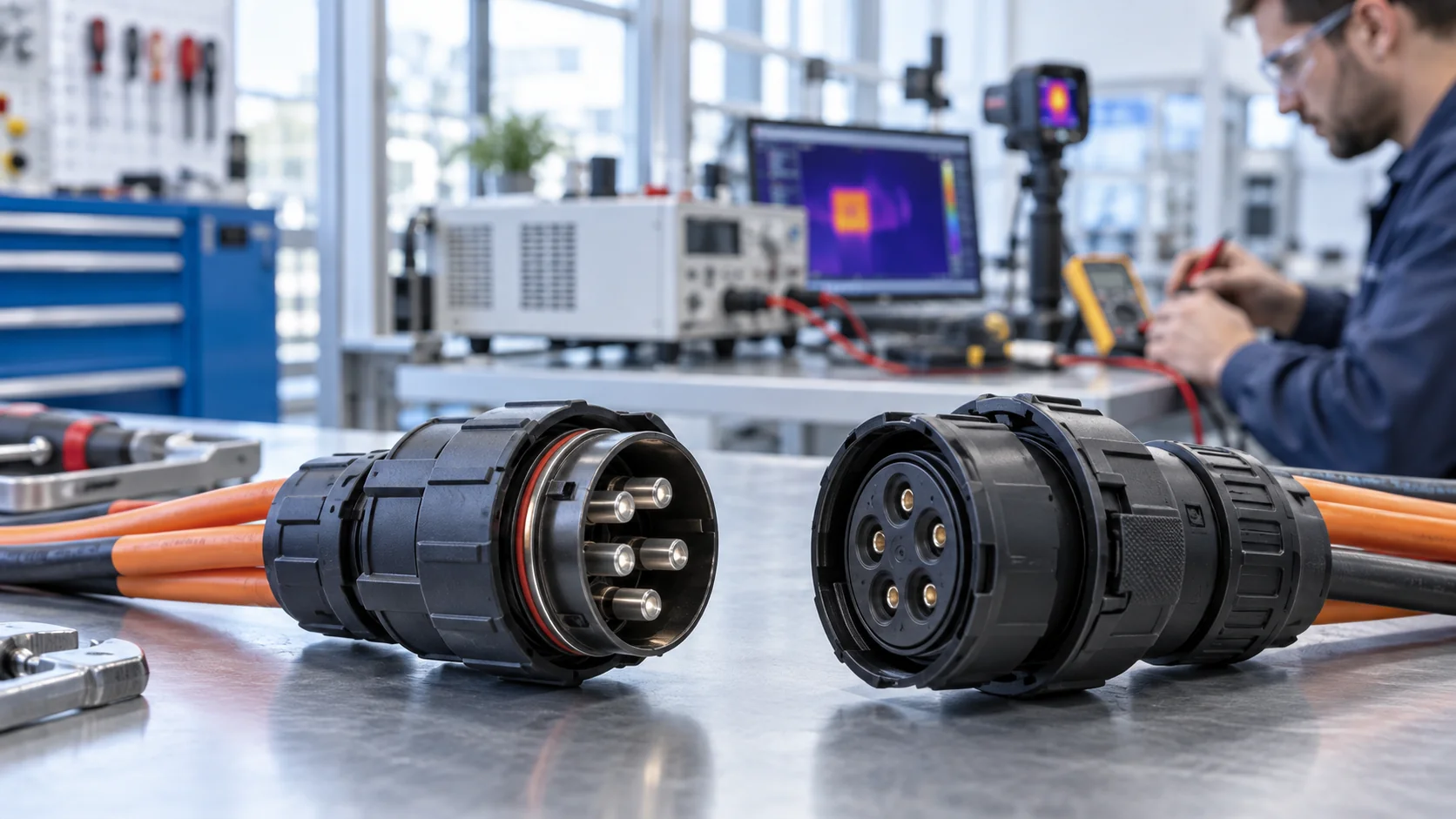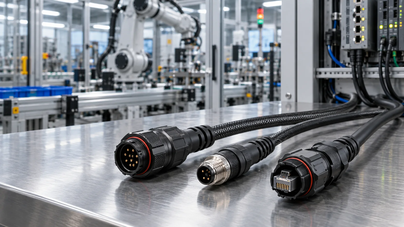
A cable assembly can pass a quick continuity check and still interrupt a machine when a connector moves, a harness bends, or production current increases. For factory OEMs, the useful question is not simply whether electricity can travel through a wire. It is whether the correct circuits remain connected, unintended paths stay isolated, and the assembly performs within its approved installation conditions.
This guide explains how to build a practical pinout, continuity, and intermittent-fault acceptance plan. It separates production screening from design qualification and helps purchasing, quality, and engineering teams give JNICON a clear specification. The examples are illustrative engineering scenarios, not claimed JNICON test results or universal acceptance limits.
What Should a Cable Assembly Test Confirm?
A useful electrical test starts with an approved definition of the product. The connector part numbers, contact numbering, wire sizes, branches, shields, and drawing revision must describe the same configuration. A test program copied from a similar harness can confidently approve the wrong product if its reference information is incorrect.
For a passive cable harness assembly, the initial checks normally address intended connections, unintended connections, and resistance where the application requires it. Mechanical inspection addresses different questions: contact retention, locking engagement, strain relief, seals, labels, and dimensional fit. Neither group replaces the other.
- Pinout: Each source contact reaches the correct destination or destinations.
- Continuity: Intended electrical paths meet their documented resistance criteria.
- Isolation: Circuits that should remain separate do not show unintended conduction.
- Intermittency: Connections remain stable during a defined, non-destructive handling procedure.
- Application performance: Power, communication, shielding, and environmental behavior meet the relevant qualification plan.
Specify which checks apply to every production unit and which apply to qualification samples or process audits. For broader configuration choices, see the custom cable assembly and wiring harness guide. This article focuses on how to verify an already defined assembly, rather than repeating general supplier selection advice.
Freeze the Drawing and Netlist Before Testing
A netlist is the list of electrical connections the finished product should contain. It should identify connector designators, contact positions, branches, splices, and intentional common connections. Wire color alone is not a reliable substitute: colors can repeat, supplier conventions differ, and a repaired harness may contain replacement conductors.
Make the connector view unambiguous
State whether each connector drawing shows the mating face or wiring side. A mirrored interpretation can reverse the apparent contact sequence even when an assembler follows the drawing carefully. Include the orientation key, cavity numbering, and reference features. Distinguish contact gender from housing descriptions instead of relying on the words plug and socket without explanation.
Document intentional shield-to-shell connections and unused contacts separately. An empty cavity is not the same thing as an installed contact that must remain electrically isolated. If a drain wire terminates only at one end, the test plan must reflect that design instead of adding an accidental second grounding path.
Before releasing custom cable assemblies, compare the drawing, bill of materials, approved sample, and tester program. A second-person engineering review can catch systematic mapping mistakes that repeated production tests will not discover. Control the program revision alongside the product revision, and withdraw obsolete adapter labels and printed work instructions when a change takes effect.
Use a Pinout Matrix That Operators Can Read
A pinout matrix translates the design into an inspectable production reference. The following simplified example describes a hypothetical six-contact interface. It is not a JNICON connector pin assignment and must not be used to wire an actual product.
| Source | Destination | Intended function | Verification note |
|---|---|---|---|
| J1 contact 1 | J2 contact 1 | Power positive | Check approved conductor size and mapping |
| J1 contact 2 | J2 contact 2 | Power return | Verify no unintended connection to shell |
| J1 contact 3 | J2 contact 3 | Signal A | Confirm pair assignment if required |
| J1 contact 4 | J2 contact 4 | Signal B | Confirm no cross-wire with Signal A |
| J1 contact 5 | J2 contact 5 | Auxiliary circuit | Use application-specific acceptance criteria |
| J1 contact 6 | No connection | Reserved | Check isolation as specified |
Add shield, shell, and branch connections as explicit rows when they are part of the design. For branched harnesses, show all destinations of a common net. Otherwise, an intentional splice can be mistaken for a short, or a missing branch can escape a test that monitors only the main connector.
Test-adapter labels should use the same connector designators as the drawing. Operators should not have to translate J1 into an undocumented fixture nickname. Keep revision and assembly identity visible at the station, especially when multiple visually similar harnesses share one tester.
Set Continuity Limits From the Actual Circuit
A buzzer indicates that a meter has recognized a conductive path under its own settings. It does not establish that the resistance is acceptable for your equipment. An overly permissive threshold can miss a degraded termination, while an unrealistic threshold can reject a correctly built long harness.
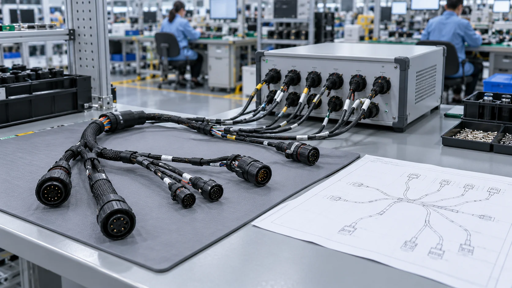
Estimate the expected path from conductor material, cross-section, length, contact interfaces, splices, and the measurement arrangement. Confirm the estimate using an approved reference assembly and a suitable instrument. Allow for defined operating and measurement conditions rather than creating an undocumented margin whenever a unit fails.
Separate fixture resistance from product resistance
Adapter cables, mating contacts, and probe interfaces can contribute to a two-wire measurement. When the decision depends on small resistance differences, ask whether a four-wire measurement and appropriate fixturing are needed. Record how fixture contributions are handled and what the reported number represents.
For a power circuit, application qualification may also require voltage-drop and temperature-rise measurements under defined load. A low-current continuity pass alone is not proof of rated-current performance. See the high-current connector overheating checklist for a separate investigation of power-path heating.
Avoid advertising a single resistance limit as suitable for every cable assembly. JNICON enquiries should include circuit function and cable length so acceptance criteria can be discussed in context.
Check Shorts, Unused Contacts, and Shield Paths
Continuity verifies intended paths. Short-circuit screening asks whether unintended paths exist between nets. Both are needed because an assembly can have a correct end-to-end connection and an unwanted bridge at the same time.
Use the approved netlist to distinguish intended common circuits from defects. In power distribution harnesses, multiple returns may share a splice by design. In signal assemblies, a shell, shield, or drain wire may follow a specific grounding arrangement. A test program that assumes every contact is independent will misinterpret those configurations.
Inspect connector cavities for loose strands, contamination, displaced contacts, and assembly damage. Verify reserved contacts and shell isolation where required. If a connector has electronic components, suppression devices, indicators, or filters, tell the test engineer before selecting test voltages or interpreting current flow. Such assemblies cannot always be treated as simple passive wires.
Low-voltage isolation screening, insulation-resistance testing, and dielectric-withstand testing are different procedures. Do not apply high voltage based on a generic internet value. The approved product specification must define the method, limits, safety controls, and component compatibility. Qualification planning should also consider whether repeated testing could affect the assembly. Electrical testing must be performed by trained personnel with suitable equipment and controlled access.
Find Intermittent Faults Without Damaging the Harness
An intermittent connection can disappear when the harness is laid flat. It may return near a branch, backshell, crimp, or connector entry when the equipment moves. A static test captures only the condition present during its measurement window.
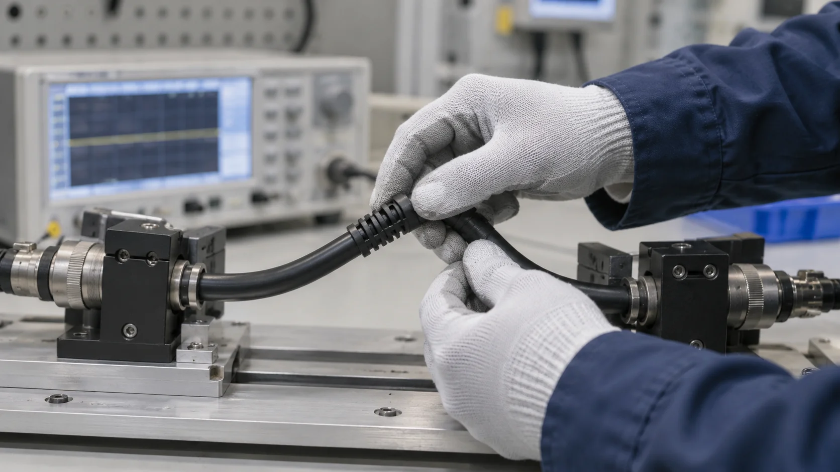
Use a tester mode capable of detecting and retaining transient events while monitoring the relevant circuits. Define the observation time, handling locations, movement range, and reporting rule. A continuous test that simply displays the final good state can hide a brief failure if it does not preserve the event.
- Confirm the fixture and reference assembly behave correctly.
- Connect the assembly and establish a stable baseline.
- Apply the approved gentle handling sequence near selected strain-relief and branch locations.
- Record the circuit, event type, and location when instability appears.
- Quarantine the assembly and investigate the cause before repeating acceptance testing.
Do not pull on individual conductors, force a connector past its stop, or bend below the approved radius. This is a defined screening procedure, not an improvised endurance test. A harness intended for continuous machine motion needs separate flex-life qualification under representative conditions.
Cirris explains that intermittent errors can originate in either the cable or its fixture, and warns against testing until movement makes a failing cable appear good. Its intermittent-fixture guidance supports checking the measurement system before blaming the product.
Validate the Fixture and Tester Program
The test fixture is part of the measurement system. A worn adapter contact can create false failures, while a miswired adapter can make an incorrect assembly appear correct. Frequent connector mating, cable movement, and contamination all deserve a maintenance plan.
Use controlled reference artifacts to verify that the program recognizes the intended wiring and known fault conditions. A single good sample proves less than a validation that also checks representative opens, cross-wires, and unintended connections. Keep those validation artifacts clearly separated from saleable production goods.
Control the complete station
Record tester identity, calibration status where applicable, adapter identity, program revision, and validation results. Establish a replacement or inspection rule for consumable mating interfaces. After fixture repair, software changes, or product revision, verify the affected configuration before returning the station to service.
If failures follow a particular station rather than a product batch, compare fixtures before increasing production rework. Swap only one controlled variable at a time and preserve the original failure information. Repeatedly reconnecting everything can erase the condition you need to diagnose.
The goal is a repeatable decision that another qualified operator can reproduce. This is also useful when comparing cable assembly manufacturers: ask how they control test programs and adapters, rather than accepting a photograph of a tester as evidence of adequate inspection.
Turn Failure Symptoms Into an Investigation Plan
Describe the symptom precisely before deciding the corrective action. An open circuit, unstable resistance, wrong destination, and communication error point to different investigations. A machine alarm alone rarely identifies the cable as the cause.
| Observed symptom | Initial checks | Evidence to retain |
|---|---|---|
| One circuit always open | Netlist, contact seating, conductor termination, adapter path | Contact pair, drawing revision, stationary reading |
| Failure appears during gentle movement | Strain relief, branch transition, contact retention, fixture wear | Handling location and retained event |
| Correct continuity but wrong machine behavior | Polarity, pin assignment, functional circuit requirements | Approved pinout and equipment configuration |
| Signal errors only during operation | Cable category, shield layout, routing, noise exposure | Operating state and communication diagnostics |
| Heating under load | Current, contact resistance, conductor size, ambient conditions | Load profile, temperature and voltage drop |
Preserve failed samples in their original condition when practical. Cleaning, opening an overmold, or replacing contacts before recording the evidence can destroy useful information. Agree on a controlled investigation and disposition process with the supplier.
For communication circuits, a correct DC map does not establish bandwidth, impedance, or transmission performance. Use the industrial data cable selection guide to connect electrical mapping with application-specific signal requirements.
Separate Production Screening From Qualification
Production screening checks individual assemblies against an approved specification. Qualification asks whether the design and manufacturing process are suitable for the intended environment. Mixing those purposes can create unnecessary costs or a false sense of confidence.
A production plan may combine dimensional and visual checks with electrical tests on each finished assembly. Qualification may address vibration, thermal exposure, sealing, flexing, contact durability, or signal performance using a defined sample plan. The required scope depends on the equipment, risk, contract, and applicable standards.
IPC identifies IPC/WHMA-A-620 as requirements and acceptance guidance for cable and wire harness assemblies. Specify the contractually applicable edition, class, and requirements with the supplier rather than treating the standard name as a complete test instruction. See IPC's cable and wire harness standard information. Referencing this standard does not mean every JNICON assembly or operator has a particular IPC certification.
Likewise, a connector ingress rating does not automatically establish the sealing performance of every cable entry, splice, or finished machine. Verify the exact configuration and test conditions. If the project has military, medical, railway, or other regulated requirements, identify them explicitly and request relevant evidence. Do not infer application approval from connector shape or a supplier's general product range.
Request a Traceable Test Record
A useful test record lets the receiving factory connect a result to a real assembly configuration. The word passed is insufficient if the test program, product revision, or covered circuits are unknown.
- Assembly part number, revision, and batch or serial identifier.
- Test date and station or equipment identification.
- Program and fixture revisions.
- Checks performed and applicable acceptance criteria.
- Measured values when required, not only an overall result.
- Failure, rework, retest, and release disposition.
Agree on record retention and delivery format before production. A sample inspection report may be enough for one project, while another requires individual electrical results. State the requirement in the purchase specification so it can be reflected in cost and lead time.
Keep first-pass failures separate from final release results. If rework makes the final yield look perfect, it can conceal a recurring process issue. For incoming inspection, match carton labels, assembly markings, and report identifiers without inventing traceability that the purchased product does not provide.
JNICON enquiries should request the evidence relevant to the planned assembly, including any customer-specific format. Confirm what will be supplied before placing an order rather than assuming that every catalogue item includes the same documentation package.
Send JNICON a Complete Testing RFQ
To discuss custom cable assemblies efficiently, send a drawing or connection matrix together with the application conditions. A photograph is useful for routing and access, but it cannot replace contact mapping, conductor details, or acceptance requirements.
Include connector families and contact arrangements, cable lengths and tolerances, wire sizes, jacket requirements, shield termination, branch dimensions, locking method, and environmental exposure. Explain whether the harness remains stationary or moves during service. Add current and voltage for power circuits and protocol requirements for data circuits.
Then define the requested inspection package: continuity and mapping coverage, isolation checks, intermittent screening, dimensional checks, qualification tests, and reporting format. Where limits are not yet established, label them as items requiring engineering agreement rather than filling the gaps with guessed numbers.
Provide prototype quantity, forecast volume, delivery stages, and change-control expectations. Ask JNICON to review the proposed connector and assembly configuration, identify unresolved requirements, and confirm the inspection scope available for that project. The review should result in an agreed configuration and documented acceptance plan before volume release.
A well-defined RFQ reduces avoidable clarification cycles and makes supplier comparisons more meaningful. It also keeps an apparently lower quotation from hiding omitted testing, documentation, or fixture costs.
Related Products

M19 9 Pin Signal Waterproof Connector 5A Push Locking IP67 for Sensor Networks
5A 9-pin push-locking waterproof signal connector with IP67 rating for sensor networks and control system data transmission.
M25 4-Pin Waterproof Connector 50A Push Locking Molded with Cable for Industrial Automation
Pre-molded 50A 4-pin push-locking waterproof connector with IP67-rated cable, ready-to-use for industrial equipment and outdoor LED lighting installations.
M28 4 Pin Waterproof Connector 60A Bayonet Locking IP67 for Power Systems
60A 4-pin bayonet-locking waterproof circular connector with IP67 rating for industrial power distribution and solar applications.
Related Solutions

Industrial Automation
Empowering smart factory infrastructures with certified power, signal, and data connectors. Engineered to withstand continuous multi-axis robotic motion, eliminate electromagnetic interference (EMI), and ensure zero-downtime performance in harsh manufacturing environments.
Explore Solutions
New Energy & Energy Storage
Safeguarding high-capacity grid infrastructures with certified high current connectors engineered to withstand massive voltage loads, minimize thermal buildup, and eliminate systemic arcing risks from cell to grid container.
Explore Solutions
Rail Transit
Empowering rolling stock, trackside signaling networks, and passenger information systems with certified heavy-duty power and signal connectors. Engineered to endure continuous dynamic vibrations, violent mechanical shocks, and extreme outdoor weathering.
Explore SolutionsFrequently Asked Questions
Conclusion: Define the Wiring, Then Verify It
A reliable cable assembly acceptance plan connects the approved drawing to the finished product. It confirms contact mapping, realistic resistance criteria, unintended-path isolation, controlled intermittent screening, and traceable records. Application qualification then addresses the stresses a static continuity check cannot reproduce.
For factory OEMs, the practical starting point is a clear netlist and a test plan that distinguishes product defects from fixture problems. Send your pinout, cable dimensions, installation conditions, and documentation requirements through the JNICON inquiry and contact page to request a technical review and quotation for the appropriate connector and cable assembly configuration.