

An aviation plug can look like a straightforward purchasing item until a replacement fails to mate, a cable entry leaks, or a maintenance technician discovers a different pin assignment. For industrial OEMs, the buying decision should start with the complete connection specification, not a familiar connector name. This guide explains how to compare mating interfaces, electrical requirements, locking systems, sealing, cable assemblies and supplier documentation before releasing a production order.
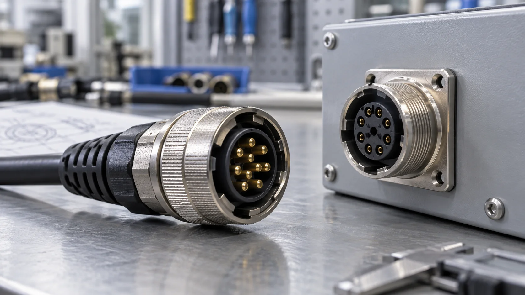
In industrial purchasing, aviation plug is a broad market term often applied to circular multipin connectors. It is not, by itself, a complete interface specification or evidence that a component is approved for aircraft. A supplier may use the term for a threaded metal connector, a waterproof polymer connector, or another circular connection family. These products can serve quite different electrical and environmental requirements.
The useful first question is therefore: what must this connection actually do? Describe the machine, circuit, mating arrangement and service environment before discussing a series name. A sensor connection on a stationary cabinet differs from a detachable power connection on outdoor equipment, even if both appear in searches under the same phrase.
Keep aircraft installation requirements separate from ordinary factory procurement. Where an actual aerospace application is involved, the responsible engineering team must identify the applicable qualification, approved part and documentation requirements. An industrial product description cannot substitute for that process. This article addresses industrial equipment selection; it does not establish suitability for flight-critical systems.
For a broader comparison of circular interfaces in factory applications, see JNICON's circular electrical connector guide.
Turn the Connector Name into a Controlled Specification
A reliable request for quotation describes the connector as an assembly of controlled parts. Specify the cable-side plug, equipment-side receptacle, contacts, seals, cable entry hardware and protective accessories. If a cable is included, identify its construction and the finished assembly drawing as well. A quotation for only the visible plug body can leave essential components outside the purchasing scope.
Record the supplier's exact series, part numbers and drawing revisions. State whether the proposal is a replacement that must mate with installed equipment or a new interface whose two halves can be selected together. Replacement projects need particularly careful identification because visual similarity may hide different contact layouts or coupling details.
Also establish the reference view for every drawing. A front mating-face view and a rear wiring-side view can appear mirrored. Showing the key orientation and numbered contacts avoids ambiguity when purchasing, assembly and inspection teams exchange documents.
For an aviation plug connector inquiry, include photographs of an existing connection only as supporting information. Ask the supplier to confirm compatibility against dimensions and part identification, rather than treating a photograph as approval. This small documentation step can prevent a prototype mistake from being repeated across an entire production batch.
Check Mating Compatibility Before Comparing Prices
Matching the number of pins is necessary but insufficient. A compatible pair also needs the correct shell geometry, contact diameter and position, keying, engagement depth and locking interface. A connector that begins to engage is not automatically a correct mate. Do not force an uncertain pair together or modify a key to make it fit.
Use a short compatibility checklist during sample review:
- Exact manufacturer and series for both mating halves.
- Contact arrangement and numbered mating-face drawing.
- Plug and receptacle gender, including contact gender.
- Coupling type and all critical interface dimensions.
- Panel opening, mounting thickness and rear clearance.
- Approved cable diameter and termination components.
Purchasing terminology can be inconsistent: some teams call a cable connector male because of its housing shape, while others mean the contacts. Put both the housing configuration and contact configuration on the drawing instead of relying on that label alone.
Request a mating sample pair for a new design and evaluate it in the real enclosure. Check clearance with neighboring connectors, tools and gloved hands. Before considering a second supplier interchangeable, obtain documented interface agreement and validate the proposed pair. A lower unit price is not useful if service spares cannot connect to the installed fleet.
Define Electrical Loads and Contact Assignments
Start electrical selection with the operating circuit, not the largest rating displayed in a catalog. Record voltage, AC or DC operation, continuous current per contact, expected peaks and how many contacts carry current simultaneously. Include ambient temperature and enclosure conditions so the supplier can assess the intended operating point against the relevant product data.
Do not assume the contact, cable and finished assembly share the same limit. Cable cross-section, termination quality and heat removal all matter. Ask for the allowable configuration and any required derating information for the exact contact arrangement. Where a catalog includes several variants, make sure the quoted values belong to the selected variant.
Assign power, protective earth, signals and shields explicitly. Reserve contacts only through a documented plan; spare positions should not create opportunities for a future technician to connect incompatible circuits. For mixed power and signal interfaces, review separation, shielding and the signal protocol with the equipment designer.
A locking connector is not automatically a load-break device. Unless the exact product and equipment procedure explicitly permit energized mating or disconnection, isolate the circuit before connection work. For additional purchasing context, consult the industrial power connector selection guide.
Choose a Locking System for the Service Routine
Threaded, bayonet and push-locking connections solve different handling problems. Instead of declaring one universally best, evaluate how operators will connect the equipment, how often the connection is serviced and how much access is available. The release method must be understandable without encouraging staff to pull on the cable.
A threaded coupling can provide a familiar controlled tightening operation, but the assembly instructions and access space matter. A bayonet arrangement can shorten the locking movement, while a push-locking design can simplify repeated handling. Actual retention, vibration performance and service life remain product-specific; the locking name alone does not establish them.
During the trial build, ask a technician to complete the documented mating and release sequence in the installed position. Check that the locked state is recognizable and that adjacent equipment does not obstruct the coupling. Confirm whether a torque instruction, alignment mark or inspection step is required.
The best selection reduces opportunities for incomplete engagement without making maintenance unnecessarily difficult. If frequent disconnection is central to the machine design, compare the workflow described in JNICON's quick-disconnect connector OEM guide. Specify the actual mating-cycle requirement and request supporting product information rather than assuming an unlimited service life.
Evaluate Sealing as a Complete Installed Connection
Waterproof performance depends on the specified assembly condition. Ask whether the published protection applies when fully mated, when fitted with an approved cap, or under another defined condition. An open receptacle is not automatically protected simply because the assembled connector carries an IP rating.
IEC 60529 provides the enclosure protection classification framework. For a purchasing decision, request the applicable product test conditions and distinguish ingress protection from separate concerns such as chemical exposure, corrosion and mechanical loading. A rating label does not answer every environmental question.
Review the full sealing path: mating interface, panel gasket, cable gland or overmold, unused openings and any protective cap. Confirm that the actual cable jacket and outside diameter are within the approved range. A sealing accessory selected for a different cable can undermine an otherwise suitable connector.
Describe the factory's cleaning and exposure conditions accurately. Occasional splash, outdoor rain, temporary immersion and high-pressure cleaning are different requirements. Do not infer suitability for one from a statement about another. Keep sealing surfaces clean during assembly and use the manufacturer's installation instructions. Where the process includes cleaning chemicals, request material compatibility information before approving the connection.

Match Cable Construction and Strain Relief to Movement
The cable is part of the connection system, not an interchangeable afterthought. Define conductor size, insulation, jacket material, shielding and the expected installation environment. Then distinguish fixed routing from repeated bending or torsion. A cable that works in a stationary cabinet may not be suitable for a moving axis.
Plan routing with the equipment assembly in its normal and service positions. Leave space for the specified bend radius, support cable weight and avoid transmitting routine pulling forces directly into contacts. A strain-relief boot does not replace external cable support where the installation requires it.
For moving equipment, provide the supplier with the motion type, travel, cycle expectations and routing constraints. Ask for evidence appropriate to that configuration. Do not transfer a flexible-cable claim to the completed aviation connector plug assembly without reviewing the terminations, connector orientation and mounting arrangement.
Shield termination should follow the equipment's EMC design rather than an improvised workshop convention. Document how the shield connects through the interface and how continuity will be checked. If the project needs a complete harness, the custom cable assembly guide explains how routing, branches and termination requirements can be captured in a controlled assembly specification.
Decide Between Field Assembly and Molded Cables
Field-installable connectors can be useful when cable lengths must be adjusted during equipment installation or service. Their performance depends on suitable tools, trained assembly staff and a clear work instruction. Specify stripping dimensions, terminal preparation, tightening requirements and inspection criteria for the exact product rather than relying on general workshop habits.
Preassembled or molded cables move more of the termination work to the supplier. This can simplify installation, but the drawing must define length measurement points, orientation, pin-to-pin connections, labeling and cable construction. The finished assembly also needs an agreed test scope; appearance alone does not demonstrate correct wiring.
Compare the two options using total production effort. Include assembly time, tooling, inspection, rework, service access and replacement logistics, not just the connector price. A fixed-length assembly may be convenient on a repeatable machine platform but inconvenient where routing varies significantly between installations.
For either route, approve a first article before volume procurement. Retain the approved drawing and sample identification, and define which changes require review. Cable substitutions, contact revisions and overmold changes should not enter production solely because a replacement appears equivalent. See the standard cable assembly guide for length and documentation considerations.
Create an Application-Based Sample Validation Plan
A useful sample evaluation starts with acceptance criteria, not a collection of impressive test names. Agree what the prototype must demonstrate and which checks are routine production tests versus design qualification tests. The required scope should reflect the machine's risk assessment, applicable requirements and operating conditions.
Begin with identification, dimensions and workmanship. Confirm the mating pair, contact assignment, cable length, labels and mounting fit. Electrical checks can include continuity and absence of unintended connections, with insulation or dielectric testing only under approved methods suitable for the assembly and any connected electronics.
Where necessary, extend validation to temperature rise, cable retention, repeated handling, vibration or environmental exposure. Specify the test conditions, acceptance limits and sample configuration. A report for a different connector variant or cable termination is not automatically evidence for the proposed assembly.
For example, consider a detachable cabinet connection on a packaging machine. A sensible review might combine a drawing check, installation trial, wiring verification, representative operating load assessment and the relevant cleaning exposure evaluation. This is an illustrative planning example, not a claimed JNICON customer case. Record findings and corrective actions so the approved configuration can be reproduced instead of depending on a technician's memory.
Compare Supplier Evidence and Total Ownership Cost
An OEM purchasing team should be able to connect each important claim to a document for the proposed part. Request the current drawing, material and cable specifications, test information, installation instructions and applicable compliance documents. Check the scope and identity of any certificate rather than treating a company logo or general quality statement as product approval.
Ask how the supplier controls revisions and substitutions. Important questions include how contacts and cables are identified, how a finished assembly is linked to its production record, and how customers are notified of changes. The level of traceability should match the project requirement and be agreed before the order.
Commercial comparison should include sample cost, tooling, minimum quantities, lead time assumptions, packaging, spare-part availability and responsibility for rejected assemblies. Request these as quotation terms; do not assume a website's general service statement is a commitment for your order.
Finally, consider the cost of an incorrect replacement in the field. Keeping one controlled mating pair and a clear service part number may reduce confusion more effectively than maintaining several look-alike alternatives. JNICON's cable assembly manufacturer evaluation guide provides a complementary framework for reviewing assembly suppliers.
Review JNICON Industrial Connector Options
JNICON's product center provides industrial circular connectors and cable assembly options that can be reviewed against an OEM's connection specification. These should be treated as industrial candidates, not as automatically interchangeable replacements for every product sold as an aviation plug. Start with the required mating arrangement and ask JNICON to identify the exact proposed configuration.
Three relevant directions are the M25 five-pin push-locking connector for multi-circuit connections, the M28 three-pin bayonet-locking family for power connections, and the M40 3+9 hybrid arrangement for combined power and signal requirements. The product cards below link to the corresponding catalog records. Confirm the current variant data and supporting documents before freezing a design; do not transfer one series' ratings to another.
Industrial automation, outdoor lighting and marine equipment each add different operating constraints. Use the related solution pages as starting points for discussing the application, then provide your actual environment, circuit and maintenance requirements. A solution category is not a substitute for part-level approval.
For a useful technical inquiry, send the mating drawing or existing part details, circuit information, cable specification, panel constraints, required environmental performance, expected quantities and sample schedule. This lets the review focus on a documented connection rather than a keyword alone.
Related Industrial Connector Products
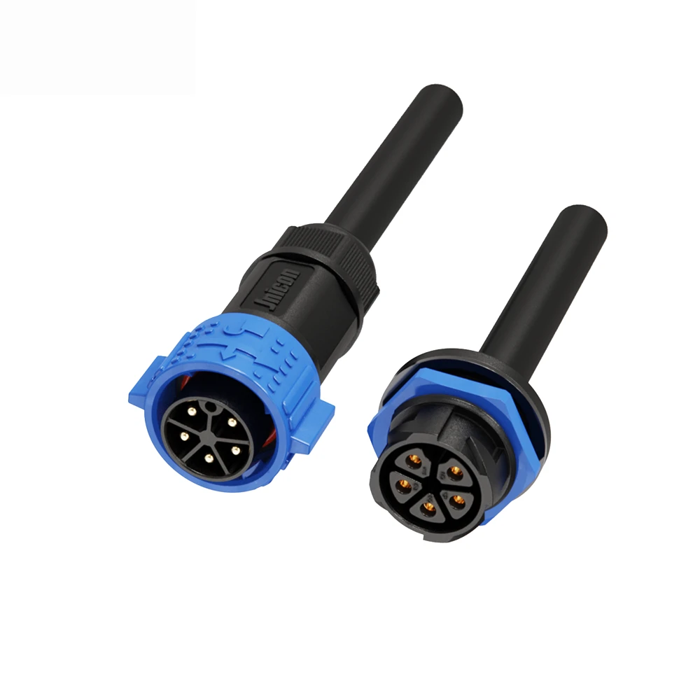
M25 5-Pin Waterproof Connector 30A Push Locking for LED Lighting & Marine
30A 5-pin push-locking waterproof power connector with IP67 protection for outdoor LED lighting and marine equipment.
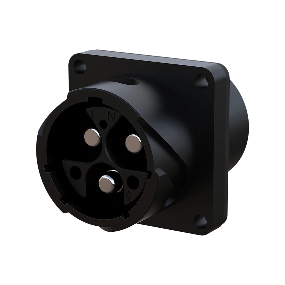
M28 3-Pin Waterproof Connector 80A Bayonet Locking IP67 for Solar & Storage
80A 3-pin bayonet-locking waterproof circular connector with IP67 rating for solar photovoltaic and energy storage systems.

M40 3+9 Pin Hybrid Waterproof Connector for Control Systems
50A+10A hybrid bayonet lock waterproof connector for industrial control and signal transmission.
Related Industrial Connection Solutions

Industrial Automation
Empowering smart factory infrastructures with certified power, signal, and data connectors. Engineered to withstand continuous multi-axis robotic motion, eliminate electromagnetic interference (EMI), and ensure zero-downtime performance in harsh manufacturing environments.
Explore Solutions
Outdoor Lighting & LED
Empowering commercial LED video walls, architectural landscape luminaires, and smart street lighting infrastructures with certified IP67/IP68 weatherproof circular connectors. Engineered to eliminate water ingress risks and endure continuous UV exposure.
Explore Solutions
Marine & Offshore
Empowering shipboard electronics, subsea exploration, and offshore oil platforms with certified heavy-duty power and signal connectors. Engineered to survive persistent marine salt spray, violent wave-shock vibrations, and extreme deep-sea liquid pressure.
Explore SolutionsAviation Plug FAQs
Conclusion: Specify the Connection, Not Just the Name
The right aviation plug for factory equipment is the one supported by a verified mating interface, appropriate electrical and environmental data, a controlled cable arrangement and an agreed validation plan. Treat the commercial name as a starting point, not a compatibility guarantee or a certification claim.
Before releasing your next order, bring the drawing, circuit requirements and service conditions into one specification. Then compare complete assemblies and supplier evidence against that specification. Contact JNICON for an industrial connector and cable assembly review and share your application details to request a project-specific quotation.


