

What Are Cable Management Accessories in Industrial Systems?
In industrial equipment, cable management accessories are the mechanical and environmental components that guide, secure, seal, identify, and protect a cable between its electrical connection points. They include cable glands, strain-relief boots, clamps, grommets, sealing rings, protective caps, conduit, braided sleeving, heat-shrink, energy chains, mounting hardware, labels, and routing supports. These parts do not carry current or data by themselves, but they strongly influence whether the complete interconnection survives installation and service.
An OEM should therefore treat cable management as part of the electrical interface, not as a late packaging task. A connector can be correctly rated while the system still fails because the cable is bent too tightly, the jacket is pulled against a sharp edge, or an enclosure entry allows vibration and moisture to reach the termination. Good accessory selection transfers mechanical load away from contacts, preserves the cable's minimum bend radius, supports sealing, and makes the assembly easier to inspect.
JNICON approaches this as an integrated connector-and-cable problem. The practical goal is to match the connector, cable outer diameter, exit direction, sealing components, attachment points, and operating environment before production drawings are released.
Why Cable Routing Failures Cost OEMs More Than Hardware
The price of a clamp or gland is small compared with the cost of a stopped machine, a field service visit, or a returned production batch. Cable failures often begin as mechanical problems: repeated flexing breaks conductor strands, vibration loosens a termination, an unsupported cable pulls on a connector, or abrasion wears through the jacket. The electrical symptom may appear later as intermittent data, voltage drop, heat, a ground fault, or an unexplained control error.
These failures are difficult to diagnose because the cable may pass a static continuity test on the bench. It fails only when the machine moves, heats up, is washed down, or is serviced. A factory customer then pays for troubleshooting time as well as replacement parts. The risk increases when different assembly operators route the same cable in different ways.
A controlled cable-management design reduces this variation. Define the approved route, support spacing, bend zones, cable-entry method, and service loop on the drawing. Add visual acceptance criteria and make the accessories part of the bill of materials. This converts an improvised installation into a repeatable assembly process that purchasing, production, and quality teams can audit.
Core Accessory Types for Connector and Cable Interfaces
The most useful accessory is the one that solves a defined load or environmental risk. Cable glands compress around the cable jacket at a panel entry and can provide sealing, pull resistance, and a controlled transition. Strain-relief boots create a gradual bend zone behind a connector. Clamps and saddles support cable weight and separate pulling force from the termination. Grommets protect jackets where cables pass through sheet metal, while conduit and braided sleeving protect longer runs from abrasion, impact, chips, and handling.
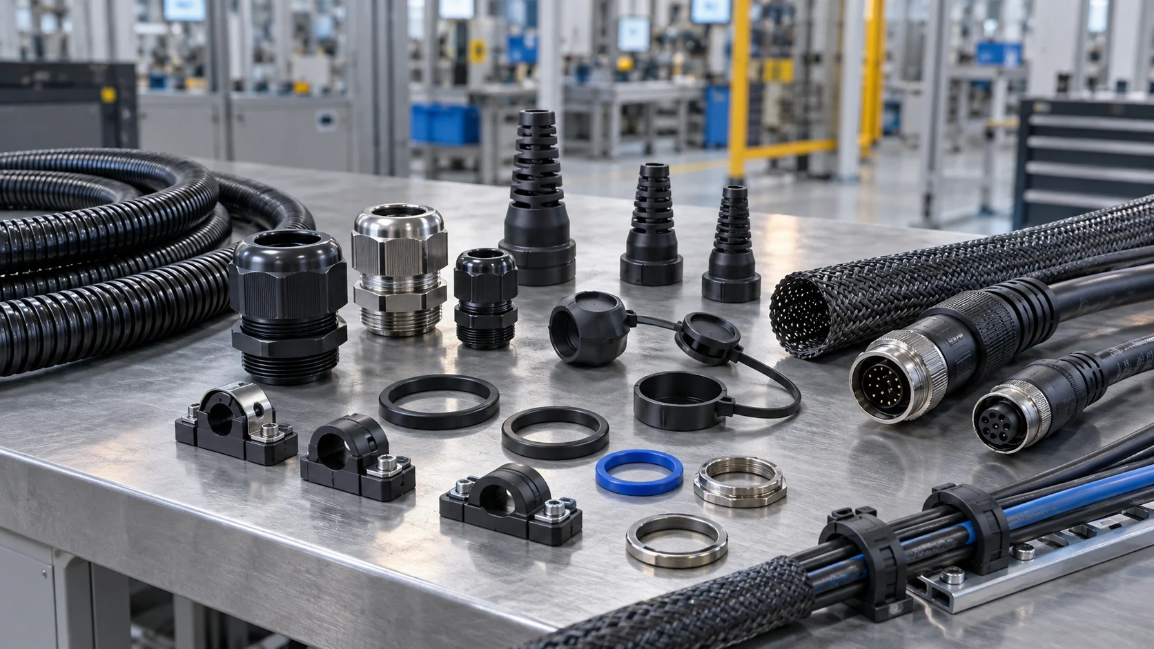
Protective caps and sealing rings are equally important at the connector interface. A cap shields an unmated receptacle from dust, splash, accidental contact, and mechanical damage. The correct sealing ring maintains compression between mating surfaces; replacing it with an incorrect size or material can compromise the intended ingress protection. Mounting nuts, brackets, and anti-rotation hardware keep panel connectors stable during repeated mating.
For a broader view of compatible accessory families, see JNICON's connector and cable product center. The central selection rule is simple: each accessory must match the connector geometry, cable diameter, mounting method, and expected service conditions.
Selecting Materials for Heat, Oil, UV, and Chemicals
Material compatibility is often more important than nominal accessory size. A polymer that performs well in a clean indoor cabinet may harden under ultraviolet exposure, swell in oil, or lose strength near a heat source. The cable jacket, gland insert, sealing ring, boot, conduit, and adhesive-lined heat-shrink should be reviewed as a material system because one incompatible component can become the weak point.
Start with the real environment rather than a generic “industrial” label. Record the minimum and maximum operating temperatures, cleaning chemicals, oils, fuels, salt spray, outdoor exposure, and expected duration of contact. Distinguish an occasional splash from continuous immersion or a daily washdown. Where chemical exposure is uncertain, request material data and conduct a representative compatibility test before approving mass production.
Also consider mechanical aging. Very rigid protection may resist impact but transfer bending stress to the cable exit. Very soft elastomers may seal well initially but creep under sustained compression. For outdoor equipment, UV stability and water absorption matter; for moving machinery, flex life and low-temperature behavior matter. JNICON can review cable jacket and sealing options against the application drawing, but final material approval should be tied to the customer's operating specification and validation plan.
Strain Relief and Bend Radius for Static Cable Runs
A static cable is not load-free. Installation pulling, cable weight, maintenance handling, vibration, and accidental contact can all reach the termination unless the route includes proper support. The first clamp or gland should carry the mechanical load before it reaches the connector. The cable should leave the connector in a natural direction without being forced against the backshell or enclosure wall.
Minimum bend radius should be based on the cable construction and supplier data, not on how tightly the installer can route it. Tight bends can deform insulation, disturb shielding, change impedance in data cables, and concentrate fatigue at the same location. Leave enough straight length behind the connector for the strain-relief boot to work, then begin the bend gradually. A service loop can help maintenance, but excessive loose cable can snag, vibrate, or block airflow.
On drawings, define the approved exit angle, clamp position, support spacing, and no-bend zone. For assemblies supplied pre-terminated, these details should be agreed with the cable assembly manufacturer so the overmold, boot, and cable length support the actual machine route rather than a generic bench layout.
Dynamic Cable Management for Robots and Moving Equipment
Robots, gantries, pick-and-place systems, and moving doors expose cables to repeated bending, torsion, acceleration, and changing loads. A standard flexible-looking cable may still fail quickly if its conductor stranding, shield construction, jacket, or filler design is not intended for continuous motion. Dynamic cable management must begin with the motion profile: travel distance, bend radius, speed, acceleration, cycles, torsion, and environmental exposure.

Energy chains guide cables through a controlled bend and prevent random whipping or snagging. Cables should be separated by size and function where needed, installed without twist, and allowed to move freely inside the chain. The chain fill should not force cables against one another. Fixed transition points need strong strain relief because movement concentrates load where the dynamic run meets stationary equipment.
For robotic applications, request flex-life evidence under conditions comparable to the real motion. A high cycle count at a large bend radius does not prove performance at a smaller radius or with torsion. JNICON can combine sealed connectors, cable selection, molded exits, and routing accessories into custom cable assemblies, but the OEM should provide the real movement envelope and acceptance target so prototype testing reflects field use.
Sealing Cable Entries for IP-Rated Enclosures
An IP-rated connector does not automatically make the entire cable entry IP-rated. Water can reach the enclosure through an undersized gland, an incompatible jacket, a loose panel nut, a damaged sealing ring, or capillary paths inside a cable. The connector, panel cutout, gasket, rear entry, and cable jacket must operate as one sealing system.
Select a gland or rear seal whose compression range matches the actual cable outer diameter, including manufacturing tolerance. Confirm that the jacket is round and firm enough to maintain uniform compression. For multi-cable entries, avoid filling unused holes with improvised materials; use the specified blanking components. Where connectors are disconnected during maintenance, fit protective caps to exposed interfaces and define how seals are inspected and replaced.
Ingress ratings are test conditions, not a universal promise for every chemical, pressure, temperature, or installation. The OEM should define whether the risk is rain, temporary immersion, dust, condensation, or high-pressure cleaning, then validate the assembled enclosure accordingly. JNICON's circular electrical connectors guide explains how connector bodies, backshells, cable diameter, and sealing geometry affect the complete interface.
Managing Power, Signal, and Data Cables Together
Mixed cable routes can create interference, thermal, and maintenance problems. High-current conductors generate magnetic fields and heat; motor-drive cables can carry fast switching noise; low-level sensor and communication cables are more sensitive. Cable-management hardware should support appropriate separation, shield continuity, and controlled crossings instead of bundling every cable into one convenient path.
Where power and data must share a route, document the allowed spacing and crossing method for the equipment architecture. Use conductive or nonconductive supports as required by grounding and isolation rules. Do not crush shielded or coaxial cables with overtightened ties. Maintain the cable geometry through glands and bend zones, and provide a deliberate shield-termination method at the connector or enclosure.
Identification also matters. Use durable labels that remain readable after cleaning and maintenance, and keep pinout, cable ID, and destination consistent across drawings and harness markings. For replacement assemblies, the label should connect the physical cable to the current revision of the BOM and test record. These steps make server rack cable management accessories and factory-machine accessories very different selection problems: the factory route must account for motion, contamination, sealing, power, and service forces, not only neat appearance.
Cable Routing in Control Cabinets and Machine Frames
Inside a control cabinet, cable routing affects airflow, service access, electrical separation, and troubleshooting. Provide wireways or supports that keep cables away from sharp edges, hot components, moving mechanisms, and terminals that require maintenance. Leave adequate space for connector mating and unmating without pulling adjacent cables. Avoid routing heavy bundles across removable panels unless a defined flexible transition is provided.
At machine frames, protect every pass-through. Deburr holes, use grommets or edge protection, and secure the cable on both sides where movement could saw the jacket against metal. Vertical routes need enough support to prevent the full cable weight from hanging on the upper termination. Outdoor frames may need drainage and drip-loop considerations so water is not directed toward an enclosure entry.
Good routing should also be buildable. If the installer cannot reach a clamp, apply the specified torque, or inspect a gland, the design will vary in production. Review the route with manufacturing and service technicians before freezing the drawing. A digital model can confirm clearance, but a physical prototype often reveals handling, tool-access, and assembly-order issues that are not obvious on screen.
Installation Standards, Drawings, and BOM Control
Consistent installation depends on clear documentation. The cable drawing should identify connector part numbers, contact layout, cable type and length, jacket diameter, exit direction, overmold or boot geometry, labels, and test requirements. The equipment drawing should identify panel cutouts, accessory part numbers, support points, bend zones, and installation notes. Reference only standards and workmanship classes that actually apply to the product and customer contract.
Make accessory part numbers explicit in the BOM. Descriptions such as “suitable cable gland” or “black cable tie” invite substitutions that may change sealing, strength, flammability, or chemical resistance. If alternates are allowed, define the technical equivalence criteria and approval process. Control revisions so purchasing does not combine an updated cable with an old gland range or an updated connector with an incompatible protective cap.
For standard-length assemblies, define where length is measured and the allowed tolerance. For custom routes, use a controlled datum at each connector face and document branch dimensions. JNICON's guide to standard cable assemblies provides additional guidance on drawings, lengths, workmanship, and acceptance documentation for repeatable OEM procurement.
Inspection and Testing Before Production Release
Inspection should verify both electrical performance and cable management. Electrical checks may include continuity, pin-to-pin mapping, insulation resistance, dielectric testing where specified, and functional signal verification. Mechanical inspection should confirm connector keying, contact retention, gland compression, boot alignment, clamp position, label accuracy, and the absence of jacket damage or sharp bends.
For sealed systems, test the assembled configuration rather than assuming that individual rated components guarantee the final result. For dynamic routes, cycle a representative prototype with the intended bend radius, load, temperature, and motion. Periodically inspect for conductor resistance change, shield degradation, jacket wear, chain damage, and movement at the termination. Record the test setup so later design changes can be compared against the same baseline.
Incoming inspection also benefits from visual standards. Approved photographs or drawings can show acceptable boot position, clamp orientation, service loop, and seal seating. First-article approval should verify the complete route on the equipment, not only the loose cable assembly. When production volume increases, these controls help JNICON and the OEM maintain the same interpretation across engineering, manufacturing, and quality teams.
How to Specify Cable Management Accessories to a Supplier
A useful request for quotation gives the supplier enough information to solve the real interface. Start with connector series or mating requirements, circuit count, voltage and current, cable construction, conductor size, shield requirements, and finished length. Add the cable outer diameter, panel thickness and cutout, mounting direction, available rear clearance, and preferred cable exit angle.
Then describe the environment: temperature range, indoor or outdoor use, dust, water, washdown, oils, chemicals, UV exposure, vibration, shock, and mechanical impact. For moving equipment, include the motion path, minimum bend radius, speed, acceleration, torsion, cycles, and energy-chain dimensions. State whether the assembly must be field-installable, pre-terminated, overmolded, labeled, bundled, or packed as an installation kit.
Finally, define deliverables and acceptance criteria. Request drawings, pinout, material information, prototype quantity, test plan, inspection report, packaging, and change-control expectations. Include forecast volume and production schedule so tooling and capacity can be evaluated early. This complete input allows JNICON to recommend cable management accessories that fit the cable and connector system instead of quoting isolated parts that may not work together.
JNICON Support for Integrated Cable and Connector Systems
JNICON supports OEM projects that require connectors, cable assemblies, and compatible accessories to operate as one installation-ready system. Relevant options include waterproof circular connectors, molded cable assemblies, dust caps, sealing rings, cable glands, strain-relief structures, mounting hardware, and customized cable length or labeling. The correct combination depends on the application drawing and must be confirmed before production.
For factory customers, integrated sourcing can reduce interface gaps between separate cable, connector, and accessory suppliers. Engineering teams can review mating compatibility, cable diameter, pinout, exit direction, sealing, and mechanical support together. Production teams receive a clearer BOM, while quality teams can define inspection around the complete assembly. This is especially useful for equipment built in multiple locations or serviced with replacement kits.
JNICON does not treat every application as identical. Share the operating environment, electrical load, installation space, movement, compliance needs, forecast volume, and validation plan. The team can then assess whether a standard component, a modified configuration, or a fully customized harness is the practical route. That application-first process helps avoid over-specification as well as hidden reliability risks.
Related Products

Circular Connector Waterproof Dustproof Rubber Protective Cap
This rubber protective cover is compatible with common circular power and signal aviation connectors. It offers two installation structures: single hole and 4-hole flange mounting. The attached lanyard prevents loss after opening, effectively blocking dust and splashing water to shield idle connector sockets from oxidation, corrosion and mechanical damage. It is a necessary supporting accessory for industrial circular connectors.

Custom OEM Wiring Harness & Cable Assembly for Medical & Industrial Equipment
We provide fully customized wiring harness & cable assembly services, covering twisted pair wires, flat ribbon cables, double-ended terminal cables, multi-core sheathed wires, USB conversion harnesses, multi-branch loom wiring, O-type ground lug cables and customized plug connection lines. Widely applied in medical instruments, industrial automation, intelligent equipment, printing devices, motor drive systems and electronic control modules, support drawing & sample personalized OEM & ODM production.
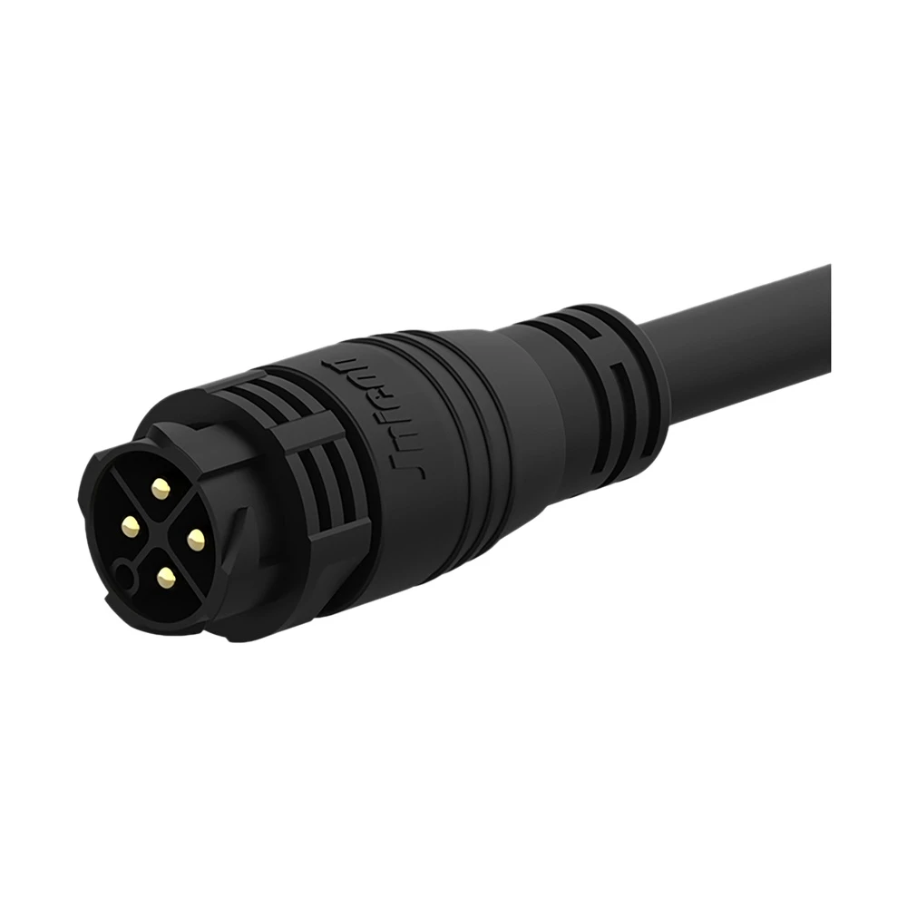
M25 4-Pin Waterproof Connector 50A Push Locking Molded with Cable for Industrial Automation
Pre-molded 50A 4-pin push-locking waterproof connector with IP67-rated cable, ready-to-use for industrial equipment and outdoor LED lighting installations.
Related Solutions

Industrial Automation
Empowering smart factory infrastructures with certified power, signal, and data connectors. Engineered to withstand continuous multi-axis robotic motion, eliminate electromagnetic interference (EMI), and ensure zero-downtime performance in harsh manufacturing environments.
Explore Solutions
Rail Transit
Empowering rolling stock, trackside signaling networks, and passenger information systems with certified heavy-duty power and signal connectors. Engineered to endure continuous dynamic vibrations, violent mechanical shocks, and extreme outdoor weathering.
Explore Solutions
Marine & Offshore
Empowering shipboard electronics, subsea exploration, and offshore oil platforms with certified heavy-duty power and signal connectors. Engineered to survive persistent marine salt spray, violent wave-shock vibrations, and extreme deep-sea liquid pressure.
Explore SolutionsFrequently Asked Questions
Conclusion: Build Cable Management into the Interface
Reliable cable management is an engineering function, not a cosmetic finishing step. The right glands, seals, boots, clamps, conduit, sleeving, caps, and routing supports protect terminations, preserve bend radius, support ingress control, and make production more repeatable. Select them with the connector, cable, enclosure, motion, and service process in mind.
If your OEM project needs integrated cable management accessories, connectors, or pre-terminated assemblies, send JNICON your drawings and operating requirements through the inquiry and contact page. The engineering team can review the interface and prepare a configuration and quotation for your application.


