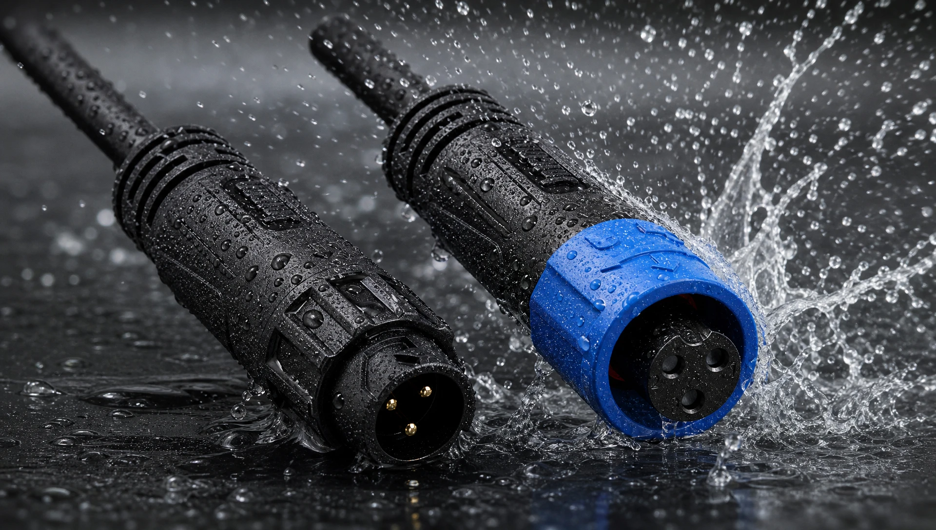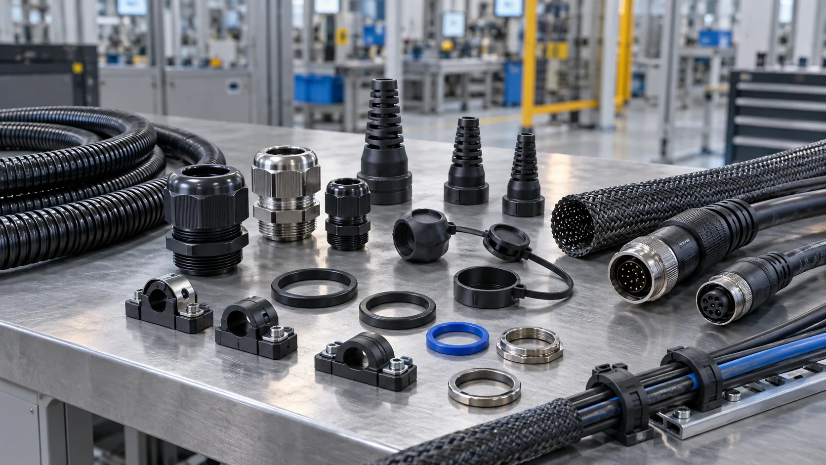
Waterproof Connector Moisture: An OEM Overview
A waterproof connector can be correctly selected and still appear in an assembly with moisture problems. For OEM engineers and quality teams, the useful question is not simply whether water is present, but where it came from. This guide separates condensation, external leakage and cable-borne moisture, then turns those findings into a practical supplier review and validation plan.
Replacing a connector with a higher advertised protection rating may leave the original failure untouched. Water could enter around a panel gasket, pass through an incorrectly sized cable gland, travel along a damaged cable, or condense from humid air already inside an enclosure. These mechanisms can produce similar visible symptoms but need different corrective actions.
Begin by defining the assembly boundary. Is the complaint about the mating interface, the cable termination, or the complete equipment enclosure? A connector test report does not automatically qualify the enclosure lid, mounting surface, cable jacket or another opening in the same system. Record the exact connector and mating-part numbers before comparing ratings.
Treat this article as a structured engineering review, not a live electrical troubleshooting procedure. Qualified personnel should isolate equipment and verify a safe state under the site procedure before opening connections or inspecting wet components. Do not re-energize a damp assembly simply because it has dried visibly. The equipment owner must decide the inspection and electrical acceptance requirements.
The goal is a reproducible explanation supported by evidence. A useful outcome identifies the entry or condensation mechanism, the conditions that trigger it, the affected production population, and the test that will demonstrate whether a proposed change works.
Condensation and Leakage Leave Different Clues
Waterproof connector condensation occurs when a surface becomes cold enough for moisture in the surrounding air to condense on it. The air may have been trapped during assembly or introduced during service. Visible droplets are therefore not, by themselves, proof that liquid crossed the connector seal.
External leakage is a different mechanism: liquid passes through an opening or an inadequately sealed interface. Possible locations include the mating seal, gland-to-jacket interface, panel gasket and damaged housing. A wet connector can also be downstream of an enclosure leak rather than its origin.
| Observation | Possible explanation | Evidence to collect |
|---|---|---|
| Fine droplets on several internal surfaces after cooling | Condensation is plausible | Temperature, humidity and operating-cycle history |
| A localized trail beside a panel opening | Panel seal or nearby enclosure leakage | Undisturbed photographs and mounting details |
| Moisture at the rear termination after cable exposure | Gland leakage or cable-borne transport | Jacket condition and remote cable-end exposure |
| Failures mainly after maintenance | Assembly condition changed | Mating, cleaning and replacement records |
These observations generate hypotheses, not verdicts. More than one mechanism can occur together. Condensation may wet a surface while a separate seal defect allows occasional leakage. Preserve the sample condition before cleaning or dismantling it.
Read the IP Rating in Its Tested Configuration
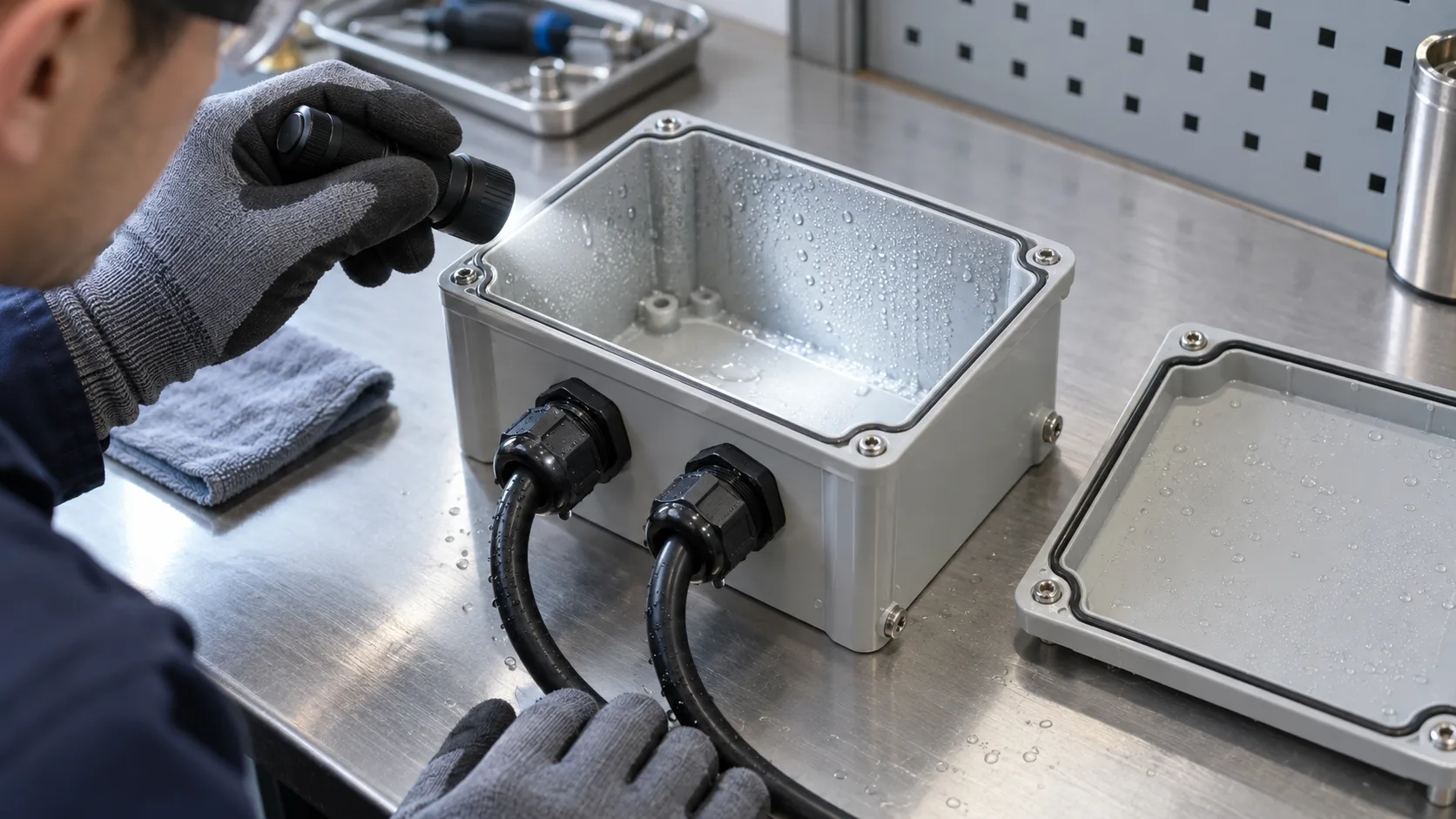
An IP67 connector designation describes specified ingress-protection conditions; it is not a blanket promise against every kind of moisture exposure. Confirm whether the rating applies when fully mated, fitted with a specified cap, or assembled using particular cable and sealing components. An unmated connector requires its own stated protection condition.
Immersion and water-jet exposure are different test categories. Do not assume that an immersion claim proves suitability for a production washdown process. Water temperature, cleaning chemicals, nozzle distance and repeated exposure can matter to the equipment assessment. For a concise manufacturer explanation of the distinction, see Phoenix Contact’s IP-rating explanation.
Request the exact test conditions and applicable assembly instructions. If a supplier quotes IP68, ask what depth and duration support that claim. If the application involves detergent or salt, establish a separate material and environmental validation requirement rather than treating the IP label as chemical-compatibility evidence.
Use the JNICON waterproof connector sourcing guide for the broader purchasing context. Here, keep the question narrower: does the tested configuration match the moisture exposure and installed assembly you actually have?
Check Cable Gland Sealing Before Changing the Connector
The cable gland seals against the outer jacket, not against the conductor cross-sectional area printed on a purchase order. Two cables with the same conductor size can have different outside diameters, jacket hardness, roundness and surface texture. A cable substitution can therefore affect sealing without changing the electrical drawing.
Compare the actual cable outside diameter with the approved gland range for the exact connector variant. Inspect for an oval jacket, cuts, molding flash, dirt, paint or labels beneath the sealing surface. A jacket that looks intact from one angle may be damaged where it bends against an equipment edge.
Follow the manufacturer’s assembly and tightening instructions. Do not apply a universal torque, extra tape or unapproved sealant as a quick remedy. Over-compression can distort components, while insufficient compression may leave a path for liquid. Any alternate seal, lubricant or adhesive needs compatibility and process approval.
A practical cable gland sealing record includes cable supplier and part number, measured diameter, seal identification, preparation method and the assembly instruction revision. Keep these details with the production lot. They help distinguish a connector design issue from a cable change or assembly variation that appeared later.
Inspect Mating Seals, Panel Gaskets and Cable Support
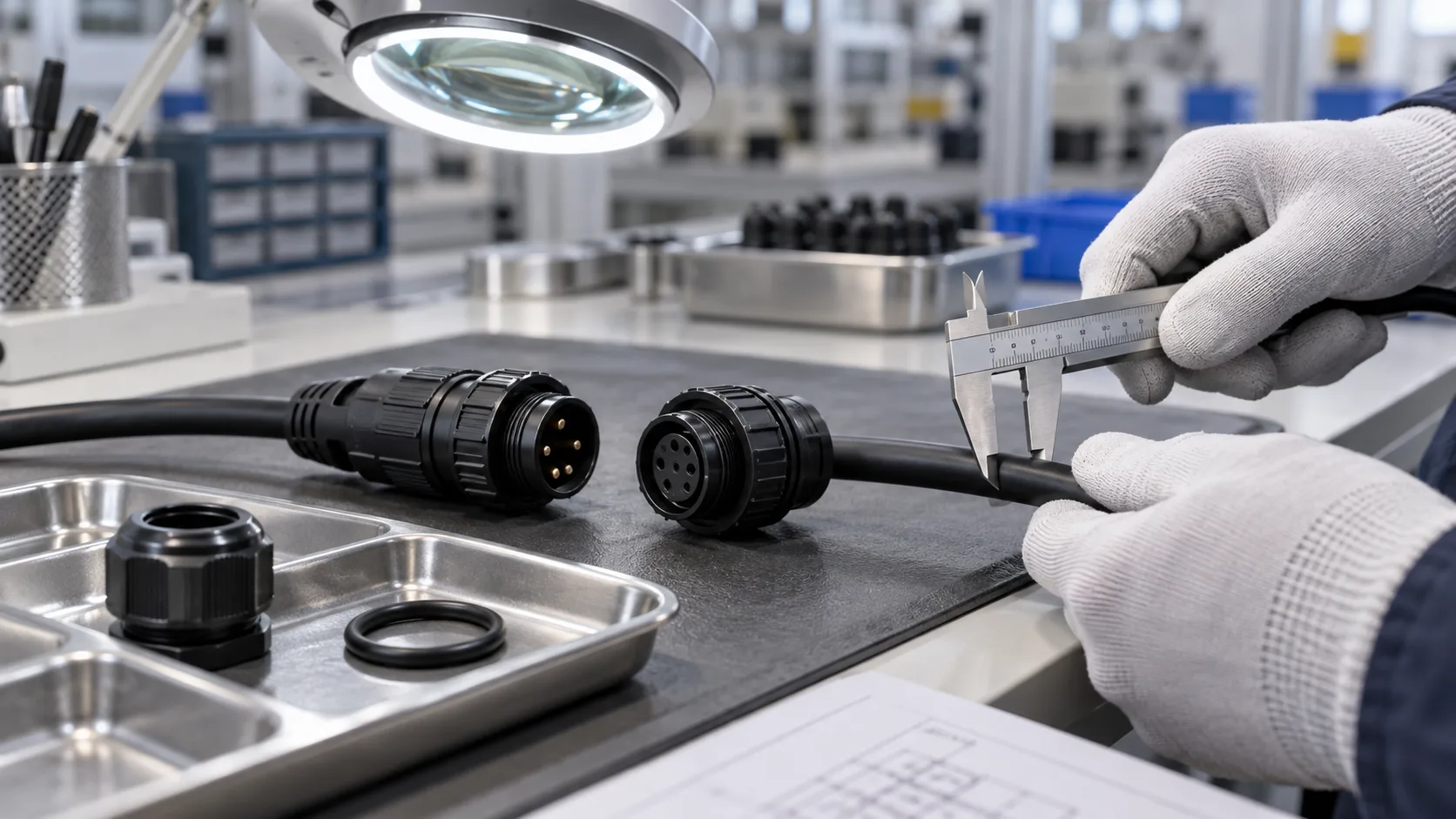
Examine the complete sealing chain. An intact mating O-ring cannot compensate for a missing panel gasket, an unsuitable mounting surface or a cable that repeatedly loads the connector sideways. Each interface needs a defined function and an installation condition that can be reproduced on the production line.
Check that the specified mating pair is used, the keying is aligned, and the locking mechanism reaches its intended engaged position. Similar shell dimensions do not establish compatibility between series or brands. Record scratches, contamination, rolled seals or pinched elastomers before attempting corrective assembly.
At the panel, review thickness, flatness, cutout dimensions and gasket seating against the drawing. A gasket crossing a burr or uneven coating may not compress consistently. At the cable exit, review bend radius, support spacing and handling loads so the sealing area is not also serving as the primary mechanical support.
For routing and support considerations, refer to the industrial cable management accessories guide. Use a drip loop only where the equipment layout and cable specifications allow it; it can manage external runoff but cannot repair a defective seal or prevent internal condensation.
Consider Moisture Transport Along the Cable
Moisture found at a connector may have entered elsewhere. An exposed cable end, damaged jacket or poorly protected splice can provide a route along the cable construction. The transport behavior depends on materials, voids, pressure differences and the assembly geometry; it should not be assumed from the cable’s appearance alone.
Map the entire route from the connector to the opposite termination. Note outdoor junctions, service loops, low points and locations where the jacket is stripped. A connector replacement at one end will not necessarily eliminate a moisture source several meters away. Keep remote-end protection within the investigation boundary.
A waterproof cable assembly may reduce some field-assembly variation, but molded construction does not automatically prove longitudinal water blocking. Ask what the supplier’s design and validation actually cover: the connector interface, cable entry, overmold bond, cable-end sealing, or the complete assembly.
When discussing a custom design, provide the cable construction and both termination conditions rather than requesting only a waterproof plug. The custom cable assembly guide outlines the information needed to define an assembly. Any water-blocking feature should have an agreed verification method and acceptance criteria before it becomes a purchasing requirement.
Review Temperature Cycling at the Enclosure Level
Outdoor and intermittently powered equipment can experience repeated heating and cooling. Air trapped during assembly may contain enough moisture to condense when internal surfaces cool. Opening a housing in humid conditions can also change its starting moisture content. A connector-only investigation misses these system-level conditions.
Capture when the symptom occurs: overnight cooling, startup, shutdown, transport, rain after heating, or a cleaning cycle. Compare the affected enclosure with a known-good unit under equivalent operating conditions. Log temperatures and humidity where appropriate; an ambient weather reading alone may not represent the air inside the equipment.
Engineered pressure-equalization vents can be part of an enclosure design, but they are not a universal repair and are not being represented here as a standard JNICON connector feature. Gore’s protective-vent FAQ explains their role in pressure equalization and reducing retained condensation. Vent selection and placement require an enclosure-level review.
Do not drill an improvised drain or ventilation hole into a qualified housing. Any change to vents, seals, heaters or moisture-control provisions must be evaluated for its effect on ingress protection, electrical safety and the equipment’s operating requirements. Keep those decisions with the responsible equipment engineer.
Use a Controlled Root-Cause Investigation
Before a failed assembly is cleaned, document its installed orientation, mating state, nearby water sources and visible moisture pattern. Assign an investigation identifier and preserve the relevant serial or lot information. Include the cable, mating half and panel interface when possible; a loose connector alone can remove the evidence needed to understand the failure.
Separate observations from assumptions in the report. “Moisture at rear termination after overnight cooling” is an observation. “Connector seal failed” is a hypothesis until the route is demonstrated. This distinction prevents a supplier discussion from becoming a debate over an unverified conclusion.
Change one controlled factor at a time where practical. Compare the specified cable with a substitute, the approved assembly method with the returned unit, or the original panel mounting with a controlled fixture. Agree the test plan before testing; uncontrolled hose spraying or improvised pressure tests can damage a sample without reproducing service conditions.
Escalate insulation-resistance, dielectric or other electrical testing to qualified personnel using suitable equipment and approved procedures. This article does not provide test voltages or pass limits. Those values must come from the applicable product specification and equipment requirements. Retain the results, sample condition and method so another team can interpret the evidence.
Validate the Fix Under the Actual Service Conditions
A proposed fix needs evidence beyond one dry inspection. Define the exposure sequence that matters to the equipment, the number and condition of samples, and the acceptance criteria. The validation should represent the intended installation without claiming that a single laboratory sequence predicts every possible field condition.
Relevant factors may include repeated mating, cable movement, temperature changes, water exposure and cleaning agents. Their order can matter: a seal that passes an ingress check when new may behave differently after mechanical handling. Avoid combining arbitrary stresses simply to make a test look severe; choose conditions that answer a specific application question.
Inspect the final configuration, not just the improved component. If the correction is a new gland insert, include the intended cable and assembly process. If it is an enclosure vent, validate the complete enclosure. If it is a molded assembly, include the cable exits and opposite termination conditions.
Record both the improvement and the limits of the evidence. A successful test supports the tested configuration under the agreed conditions; it does not establish universal washdown, immersion or chemical resistance. Obtain approval of the revised drawing, bill of materials and acceptance plan before releasing the change into production.
Turn the Findings into Purchasing and Assembly Controls
Prevent recurrence by translating the investigation into controlled information. A purchase description such as “IP67 round plug” leaves too many choices open. Specify the connector and mating-part numbers, cable range, required seals, termination method, drawing revision and applicable environmental evidence.
Define which substitutions need approval. Cable jackets, gland inserts, seal materials and molding compounds may affect performance even when the external appearance is unchanged. Procurement should know when a proposed alternative requires an engineering review instead of assuming that the original qualification transfers automatically.
Production instructions should make critical assembly checks visible: correct components, clean sealing surfaces, approved preparation dimensions, complete locking engagement and the prescribed tightening method. Inspection records need enough detail to trace a failed unit back to materials and process conditions without collecting irrelevant paperwork.
Use the supplier discussion to close evidence gaps rather than request unsupported guarantees. Ask for the applicable drawing, test scope and installation instructions, then compare them with your application. For wider supplier evaluation, the cable assembly manufacturers guide provides a complementary review framework. Connector sealing and assembly consistency should remain explicit acceptance topics.
Prepare a Useful JNICON Design Review Request
When contacting JNICON about connector water ingress, send a concise evidence package rather than only a close-up of a wet plug. Include the connector and mating-half identification, cable part number and outside diameter, panel drawing, installation orientation and the conditions preceding the fault.
Add photographs before disassembly, relevant lot information, operating current and voltage, and the environmental requirements. State whether the problem occurs with new assemblies, after maintenance or only after a particular exposure. Remove unrelated personal or commercially sensitive information from shared photographs and records.
Ask JNICON to review the connector interface and cable assembly requirements, identify candidate configurations and clarify the available documentation for the proposed part. A catalog model is a starting point, not proof that it resolves the observed failure. Samples should be assessed within the agreed equipment-level validation plan.
A clear request separates three decisions: which moisture mechanism the evidence supports, which design or process change addresses it, and which result will demonstrate acceptance. That structure makes quotations easier to compare and reduces the risk of purchasing a different connector while leaving the actual source of moisture unchanged.
Separate mandatory requirements from preferences in the request. Identify which cable dimensions are measured, which enclosure temperatures are recorded, and which exposure conditions are estimates. If the original failed sample is unavailable, say so rather than presenting a suspected leakage path as proven. Include the approved drawing revision and any recent supplier or assembly changes. This makes it easier to compare the original configuration with a proposed replacement and prevents a quotation from becoming an unsupported reliability claim. Agree on the evidence needed for approval before ordering production quantities, including who will perform the assembly-level validation and how results will be documented.
Related JNICON Connector Configurations
These JNICON configurations provide starting points for reviewing mating interfaces, cable exits and assembly choices. Select the exact part against the electrical load, cable dimensions and installation requirements. None of the models below should be treated as a proven remedy for condensation without assembly-level investigation and validation.

M19 5 Pin Waterproof Connector 15A Push Locking IP67 for Power Systems
15A 5 pin push-locking waterproof circular connector with IP67 rating for industrial power and marine systems.
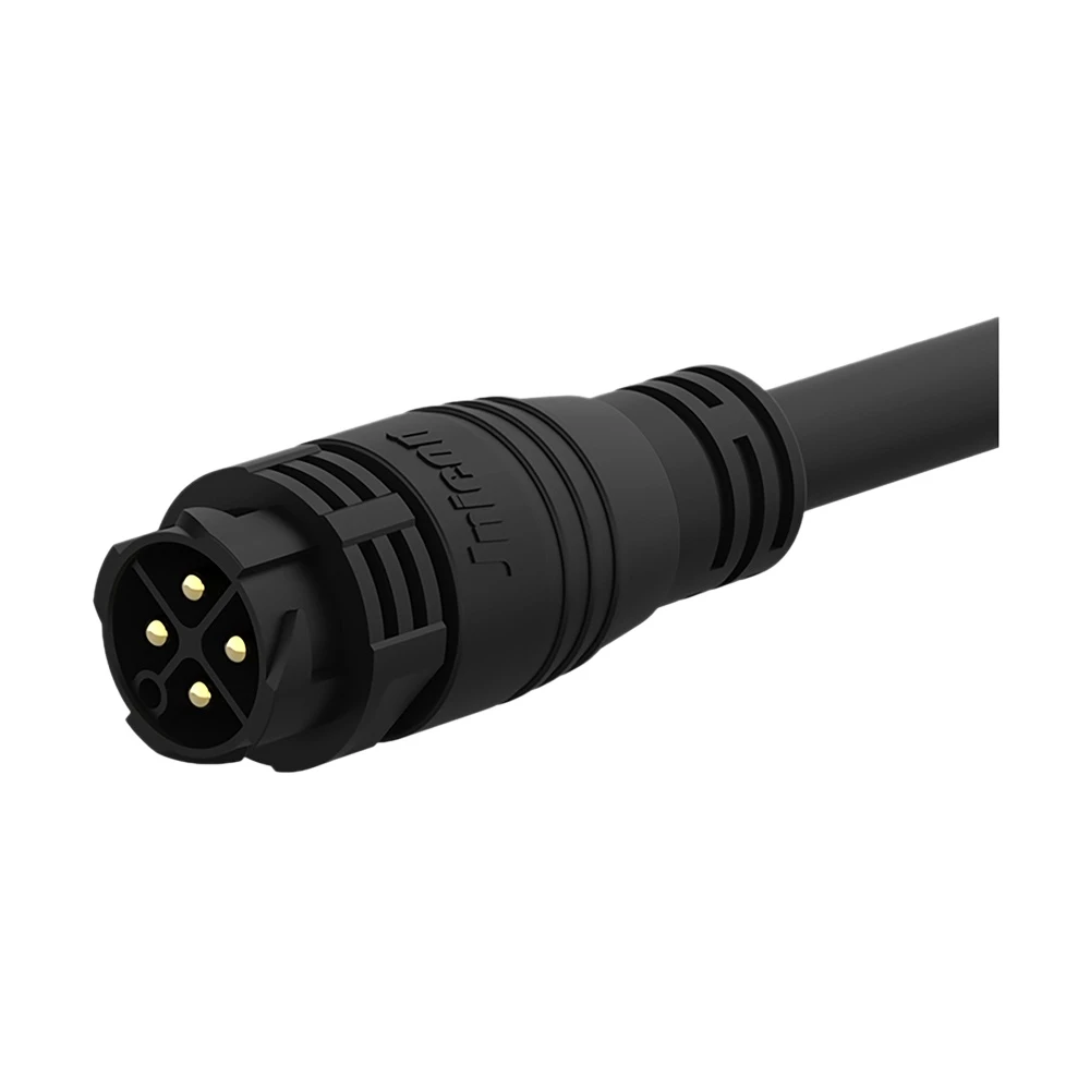
M25 4-Pin Waterproof Connector 50A Push Locking Molded with Cable for Industrial Automation
Pre-molded 50A 4-pin push-locking waterproof connector with IP67-rated cable, ready-to-use for industrial equipment and outdoor LED lighting installations.

M28 5 Pin Waterproof Connector 40A Bayonet Locking IP67 for LED Lighting & Control
40A 5-pin bayonet-locking waterproof circular connector with IP67 rating for outdoor LED lighting and industrial control systems.
Related Application Solutions
Industrial automation, outdoor lighting and marine installations expose assemblies to different combinations of humidity, cooling, runoff and cleaning. Use these application pages to frame the operating environment, then confirm the limits for the exact connector and installed assembly. Broad application descriptions do not establish chemical resistance, submersion depth or a guarantee against downtime or water ingress.

Industrial Automation
Empowering smart factory infrastructures with certified power, signal, and data connectors. Engineered to withstand continuous multi-axis robotic motion, eliminate electromagnetic interference (EMI), and ensure zero-downtime performance in harsh manufacturing environments.
Explore Solutions
Outdoor Lighting & LED
Empowering commercial LED video walls, architectural landscape luminaires, and smart street lighting infrastructures with certified IP67/IP68 weatherproof circular connectors. Engineered to eliminate water ingress risks and endure continuous UV exposure.
Explore Solutions
Marine & Offshore
Empowering shipboard electronics, subsea exploration, and offshore oil platforms with certified heavy-duty power and signal connectors. Engineered to survive persistent marine salt spray, violent wave-shock vibrations, and extreme deep-sea liquid pressure.
Explore SolutionsWaterproof Connector Moisture FAQ
Conclusion: Diagnose the Path Before Specifying the Fix
A reliable waterproof connector investigation begins with the moisture path. Separate condensation from external leakage, examine the whole sealing chain and cable route, and validate the proposed change in its installed configuration. A higher IP number cannot replace that evidence.
For a connector or cable assembly review, contact JNICON with your drawings and moisture-failure details. Include the mating pair, cable dimensions and service conditions so the discussion can focus on an appropriate configuration, supporting documentation and a practical OEM quotation.