

Choosing a medical connector for a diagnostic instrument is a system-level decision: one interface must support dependable power or signal transfer, safe handling, cleaning exposure, service cycles, and repeatable assembly. This guide gives medical-equipment OEM engineers a practical way to define requirements, compare connector and cable options, and qualify a supplier without treating a component rating as proof that an entire device is compliant.
Define the connector by the device workflow
A medical connector should be specified from the equipment workflow, not from a catalog photograph. Begin with a simple map of every place where a person connects, disconnects, cleans, moves, or services the instrument. A bedside monitor has different external interfaces from a fixed laboratory analyzer. A handheld diagnostic unit may be unplugged many times a day, while an internal power link may never be touched after final assembly. Those differences change the sensible choices for housing, latching, cable exit, labeling, and service access.
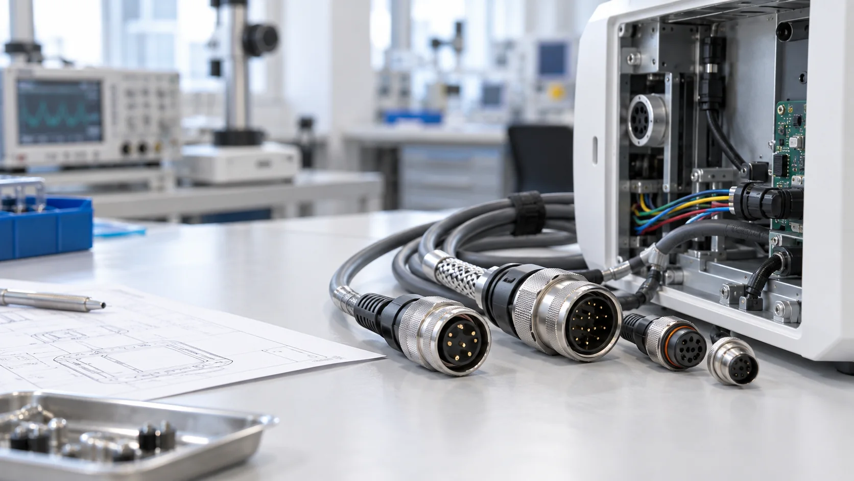
Separate the interfaces into power, low-level analog signal, digital data, and any combined power-signal connection. For each interface, record nominal and maximum voltage and current, pin count, allowed envelope, orientation, expected mating cycles, and whether disconnection is permitted while energized. Mark whether the connection is inside a protected enclosure, exposed to routine wipe-down, or likely to encounter splashes. The equipment manufacturer must define applicable safety and regulatory requirements; a connector supplier can then propose a component and evidence package against those requirements.
Before requesting samples, write down who will mate the connector and under what conditions. Gloves, poor lighting, limited clearance, and field replacement all affect usability. JNICON's medical equipment solution is a useful starting point for discussing internal harnesses, panel interfaces, and custom assembly options, but the final design should be reviewed against the OEM's own device risk file.
Separate electrical ratings from system safety
Current and voltage ratings are necessary but insufficient. A connector may carry the specified steady-state current on a bench and still run too warm inside a compact enclosure with multiple loaded contacts. Ask for the rating conditions: contact size, wire gauge, ambient temperature, number of simultaneously energized pins, and test method. Apply the same scrutiny to insulation resistance, dielectric withstand, and contact resistance. The OEM should test the chosen mating pair at the actual load and after environmental conditioning, not merely accept a nominal catalog value.
For a low-level sensor path, contact resistance stability and shielding may matter more than headline current capacity. For a power input, creepage, clearance, touch protection, strain relief, and reliable protective-earth continuity can dominate. If signals and power share one shell, review pin assignment, separation, return paths, and the likely effects of switching noise. A medical electrical connector that is suitable for one instrument is not automatically appropriate for another just because both are described as medical equipment.
Discuss fault cases early. What happens if a user tries to mate the wrong cable, the cable is pulled, a seal is omitted, or the connector is partly engaged? A keyed interface, positive latch, captive cap, or distinctive cable marking can reduce errors, but its effectiveness must be demonstrated in the full product. Ask JNICON for drawings and sample assemblies so electrical and mechanical assumptions can be tested before the OEM freezes its device design.
Choose a mating mechanism users can verify
Connector mechanics directly influence setup time and field failures. Screw locking can be appropriate where secure retention is important and access is available, but assembly torque and the chance of cross-threading must be considered. Bayonet designs can provide tactile engagement, yet the team should verify that the lock is easy to operate with gloves. Push-pull styles may speed repetitive connection, provided accidental release is controlled. No one locking mechanism is universally best for every medical instrument.
For externally accessible medical connectors, test whether an operator can identify the correct orientation without inspecting tiny markings. A keyed shell, color cue, asymmetric profile, or clear mating indicator may help. Confirm that the operator cannot confuse a power cable with a signal cable of similar size. Prototype evaluation should include actual staff who set up and clean the device, not just designers at a desk. Note the force required to mate and unmate, the grip area, and the space occupied by the connector when the cable bends.
Retention must also survive the use scenario. Pull tests, repeated mating, vibration, and cable-side strain relief should be evaluated together. A robust shell is not enough if the termination or overmold becomes the weakest point. For a serviceable device, plan replacement tooling and spare-cable identification before volume production. A reliable interface is one the OEM can assemble, inspect, and replace consistently.
Specify cleaning exposure without overclaiming
Many medical-equipment connectors encounter disinfectant wipes, hand contact, or intermittent splashes. These are distinct exposures. Ask the OEM to list the cleaning agents, concentration, contact time, frequency, and whether the connector is mated or unmated during cleaning. Material compatibility should be verified on actual housing, seal, label, and overmold samples after repeated cycles. A housing that looks acceptable after a single wipe may show stress cracking, discoloration, swelling, or loss of latch strength over time.
An IP rating describes performance under a defined ingress test; it does not prove resistance to a particular chemical, steam cycle, or sterilization process. Likewise, a sealed mated pair may not protect the open socket during cleaning. If an unmated interface is exposed, consider a cap and validate the cap's fit and retention. The design review should also address trapped liquid around panel cutouts and the route by which fluid could reach an enclosure, especially when cables slope toward the device.
JNICON's product range includes waterproof circular interfaces, but the relevant rating and materials should be checked on the selected model and mating configuration. Do not label a standard industrial connector as sterile, biocompatible, or suitable for patient contact unless its documented configuration and the final device assessment support that claim. This distinction protects both the OEM's qualification work and the credibility of the supply chain.
Protect signal quality and manage EMI
Diagnostic equipment often combines sensitive measurements with switching supplies, displays, motors, and digital communication. A connector alone cannot solve an electromagnetic interference problem, but its contact arrangement and cable termination can make the problem easier or harder to control. Start with the full signal path: sensor, cable, connector, board entry, return conductor, and enclosure bonding. Decide whether a shield is needed and exactly where it should terminate. An unplanned shield pigtail or long exposed conductor can undermine an otherwise sound cable choice.
For low-noise analog channels, specify the acceptable noise floor, contact stability, crosstalk, and grounding scheme. For high-speed data, control impedance where relevant and validate the complete mated cable assembly rather than a connector in isolation. If power and data share a shell, place the contacts and returns intentionally. A hybrid layout may reduce the number of separate cables on a compact instrument, but the integration benefit must be weighed against the difficulty of isolation, repair, and qualification.
A practical prototype review uses real cable lengths and routing. Test with the device operating in its noisiest modes and with the cable flexed near the exit. The JNICON cable assembly guide explains how terminations and harness documentation affect repeatability. Request a matched connector-and-cable sample when the assembly is the deliverable, rather than evaluating loose components independently.
Design the cable exit for real movement
Connector selection is incomplete until the cable exit is defined. A panel connector with a sharp cable turn can place continuous stress on the rear termination. A portable cart can pull a cable across an edge, while a moving probe lead may flex at the overmold hundreds of times during normal use. Sketch the installed geometry at the device, including nearby handles, hinges, service doors, and cleaning access. Specify minimum bend radius, allowed cable pull, and the expected movement profile.
For custom medical connector projects, an overmold, backshell, clamp, or separate strain-relief feature may be appropriate. The choice depends on the cable jacket, conductor count, sealing concept, and ability to inspect the termination. The drawing should define cable orientation and exit angle as clearly as it defines contact pinout. Otherwise, a correct electrical sample can arrive with a cable route that cannot be installed inside the enclosure.
Dynamic cables require more than a one-time continuity check. Run flex testing in the intended direction and radius, under realistic load, then inspect for rising resistance or intermittent opens. Include both the connector body and the first section of cable in the test. JNICON can discuss custom harness layouts for diagnostic and industrial equipment; the OEM should provide movement and life-cycle targets so the proposed assembly can be evaluated against its actual duty.
Create a drawing that controls the whole assembly
The engineering drawing should be the common reference for the OEM, connector supplier, cable assembler, and incoming-inspection team. Specify the shell and insert part numbers, contact cavity map, pin functions, mating view, wire gauge, conductor color or identification, cable construction, finished length, and length tolerance. Include the mating connector, panel cutout, sealing surfaces, torque or locking instructions, and any backshell or cap. A drawing that says only “six-pin waterproof connector” leaves too many choices to be made on the production floor.
Define critical characteristics separately from descriptive dimensions. Critical items might include contact resistance, polarity, shield termination, latch engagement, strain relief, and an optical or electrical inspection point. State the acceptance method for each. When a connector is supplied as part of a harness, identify the test boundary: bare component, terminated cable, or fully mated pair. Without this distinction, two reports can both say “passed” while covering different risks.
Revision control deserves equal attention. Assign drawing and bill-of-material revisions, keep an approved sample, and require a documented review when a contact plating, seal, cable jacket, or process step changes. For global sourcing, confirm how substitutions will be communicated and approved. JNICON should receive the latest controlled drawing and use it to confirm feasibility, tooling needs, lead time, and inspection records before any volume commitment is made.
Validate a sample before committing to production
Sample approval should be a planned sequence, not a quick visual check. Begin with dimensional and fit verification on the actual device panel and mating half. Confirm full insertion, locking feedback, operator access, cable routing, and service removal. Next, perform the electrical tests that matter for the application: continuity, pin mapping, insulation resistance, dielectric withstand where appropriate, loaded temperature rise, and signal integrity or shielding checks. The OEM sets limits from its system requirements rather than relying on a generic pass label.
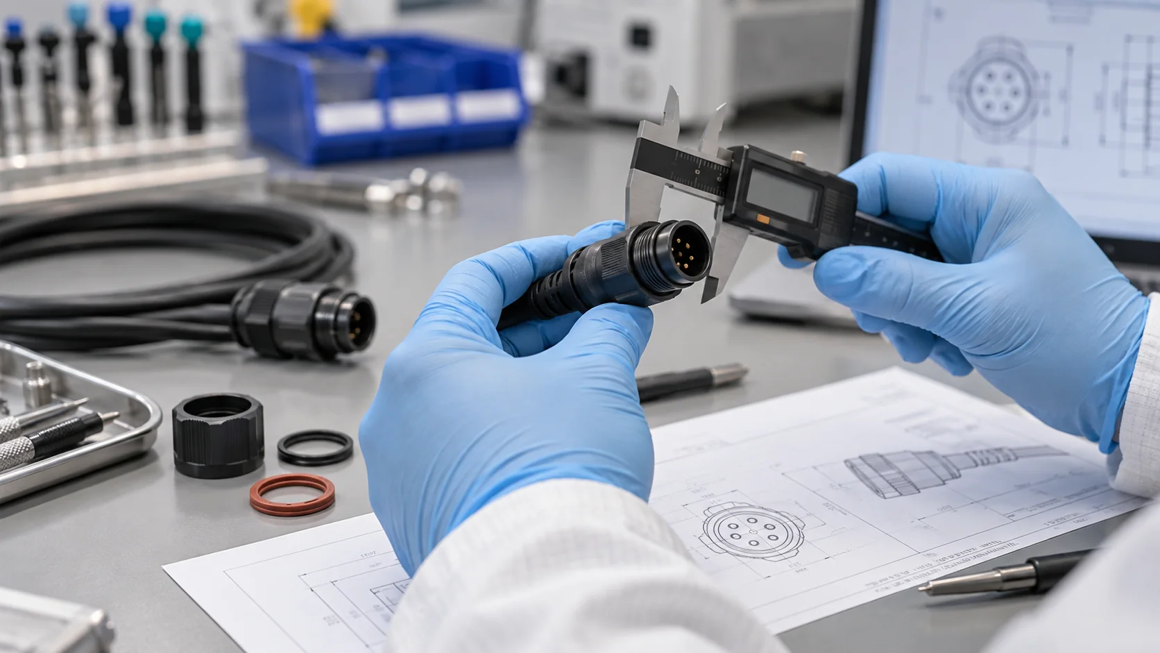
Then expose samples to the conditions the device will see. Depending on the use case, this may include repeated mating, cable flex, vibration, cleaning-agent contact, humidity, or the ingress test relevant to the mated configuration. Evaluate the assembly again after conditioning. A connector that passes only before environmental exposure has not demonstrated field robustness. Record sample identity, test configuration, equipment, limits, results, and any deviations so a later production lot can be compared with the approved design.
For equipment used in regulated settings, component qualification is one input to device-level verification. It does not replace the OEM's system risk management, electrical safety work, usability assessment, or regulatory submission. Ask a medical connector manufacturer for the evidence it can genuinely provide, and keep the boundary of responsibility explicit. This prevents a catalog statement from being mistaken for completed device certification.
Compare suppliers on evidence and change control
Quotes for apparently similar connectors can hide major differences. A lower unit price may exclude mating halves, assembly labor, special tooling, test reports, or a protective cap. Compare total installed cost and the cost of controlling a change. Ask each supplier whether the proposed part is standard or customized, who owns the tool, what the minimum order quantity is, and how sample and production lead times differ. Confirm whether the supplier will ship loose components, terminated cables, or tested assemblies.
Evaluation of medical connector manufacturers should include drawings, component traceability, lot identification, incoming material controls, assembly instructions, and a clear process for deviations. Request a sample inspection report that shows actual measured data where feasible. Ask how changes to materials, plating, molds, or sub-suppliers are notified. If the device will remain in the field for years, continuity of supply and spare-cable compatibility may be as important as initial price.
JNICON's published medical equipment page describes custom harness support and project documentation. Use that as a discussion starting point, not a substitute for a project-specific evidence request. Send the team the OEM's requirement sheet, expected volumes, target milestones, and environmental conditions. A precise request makes it easier to compare JNICON's proposal with alternatives on fit, test coverage, and manufacturing readiness rather than on marketing language.
Avoid common specification mistakes
Several recurring mistakes create expensive redesigns. The first is selecting by shell diameter and pin count alone. Two connectors that look alike may use different keying, contact systems, sealing methods, or panel cutouts. The second is quoting an ingress rating without checking whether it applies only when fully mated, with the correct gasket, cable diameter, and assembly process. The third is treating cleaning resistance as equivalent to sterilization compatibility. These are separate conditions and require separate evidence.
Another mistake is leaving pinout and cable construction open until after the enclosure has been designed. A late change in wire gauge or shield termination can alter bend radius, gland fit, thermal performance, and rear clearance. Teams also overlook human factors: a latch may pass a pull test but be hard for a gloved operator to release, or two adjacent ports may accept visually similar leads. Finally, test reports may be accepted without recording the tested revision, sample count, or mating half.
A short design-review checklist reduces these errors. Confirm use scenario, actual loads, contact layout, protective measures, housing and seal materials, cable exit, cleaning exposure, assembly method, mating life, and validation plan. Review the same list with purchasing and service personnel so decisions are not isolated within engineering. The result should be a documented medical connector specification that can be reproduced in production and understood years later during maintenance.
Use a practical RFQ package and next-step decision
A useful request for quotation gives the supplier enough information to propose a credible design. Include the device category and a high-level application description; voltage, current, signal type, contact count, preferred locking style, and available space; the mating and unmated exposure conditions; cable length and routing; cleaning agents; expected mating cycles; annual volume; qualification schedule; and required drawings or inspection records. Mark assumptions that are still undecided so the supplier can flag them instead of guessing.
For a custom proposal, request a dimensional drawing, pinout, materials, proposed cable construction, sample plan, tooling implications, lead time, and production inspection approach. Ask which claims apply to the exact configuration and which still require OEM validation. When comparing offers, use the same checklist for every candidate. An inexpensive connector with unclear change control or insufficient test evidence can consume more engineering time than its purchase-price saving.
JNICON can review a controlled specification and suggest suitable circular connectors or custom cable assemblies for equipment OEMs. Start with a prototype quantity and a small, explicit verification plan. If testing reveals a gap, revise the drawing before scaling the order. This staged approach makes the final supplier choice defensible to engineering, quality, procurement, and service teams, while avoiding unsupported assumptions about the finished medical device.
Related Products for Medical Equipment OEMs

Custom OEM Wiring Harness & Cable Assembly for Medical & Industrial Equipment
We provide fully customized wiring harness & cable assembly services, covering twisted pair wires, flat ribbon cables, double-ended terminal cables, multi-core sheathed wires, USB conversion harnesses, multi-branch loom wiring, O-type ground lug cables and customized plug connection lines. Widely applied in medical instruments, industrial automation, intelligent equipment, printing devices, motor drive systems and electronic control modules, support drawing & sample personalized OEM & ODM production.

M16 8Pin Signal Waterproof Connector 5A Screw Locking IP68 for Sensor Networks
5A 8 pin screw-locking waterproof signal connector with IP68 rating, field installable or molded with cable for sensor arrays and fieldbus systems.

Circular Connector Waterproof Dustproof Rubber Protective Cap
This rubber protective cover is compatible with common circular power and signal aviation connectors. It offers two installation structures: single hole and 4-hole flange mounting. The attached lanyard prevents loss after opening, effectively blocking dust and splashing water to shield idle connector sockets from oxidation, corrosion and mechanical damage. It is a necessary supporting accessory for industrial circular connectors.
Related Solutions

Medical Equipment
Safeguarding critical clinical operations with medical-grade certified connectors engineered to ensure zero signal latency, resist harsh chemical sterilization, and eliminate accidental uncoupling risks from bedside monitors to surgical tools.
Explore Solutions
Industrial Automation
Empowering smart factory infrastructures with certified power, signal, and data connectors. Engineered to withstand continuous multi-axis robotic motion, eliminate electromagnetic interference (EMI), and ensure zero-downtime performance in harsh manufacturing environments.
Explore Solutions
Security & Safety
Empowering outdoor IP surveillance, smart access control, and emergency alarm infrastructures with certified, compact, weatherproof power and signal connectors. Engineered to guarantee zero signal dropouts and absolute data integrity in harsh environmental conditions.
Explore SolutionsFrequently Asked Questions
Conclusion: Qualify the Interface, Not Just the Part
Choosing a medical connector is a sequence of documented decisions: define the device workflow, specify electrical and mechanical limits, validate cleaning and cable movement, and inspect the complete assembly before production release. The strongest supplier proposal is the one that matches a controlled drawing and explains what has actually been tested. Component data supports the decision, but it cannot replace the OEM’s device-level verification.
JNICON can discuss circular interfaces, custom wiring harnesses, and sample assemblies for medical-equipment OEM programs. Send your drawing, pinout, operating conditions, expected quantities, and qualification needs through the JNICON inquiry page. The team can review fit, configuration, documentation, and quotation details for your project.


