

What an Industrial Data Cable Must Deliver
An industrial data cable is not defined only by connector shape or conductor count. It is a complete transmission path that includes the conductors, insulation, pair geometry, shielding, jacket, terminations, mating connectors and installation method. Each part can change impedance, attenuation, crosstalk, grounding behavior and mechanical life. Factory buyers therefore need to purchase a controlled assembly, not a loose collection of parts that merely fit together.
Start by describing what must cross the interface: Ethernet packets, encoder feedback, serial data, sensor signals, video, USB, a proprietary differential pair or a mixture of power and low-level signals. Record the required data rate, topology, cable length, permitted latency, equipment environment and expected movement. A cable that passes a short bench test may become unreliable beside a variable-frequency drive, inside a moving robot dress pack or after repeated washdown cycles.
The practical goal is stable communication over the equipment's real service life. That means the link must meet electrical performance targets while also resisting pull, bend, torsion, vibration, temperature change, oil, moisture and operator handling. JNICON can review connectorized cable requirements for industrial equipment, but the OEM should supply the protocol, pin map and operating conditions so the proposed construction can be checked against the released design.
Start With the Protocol and Interface
Protocol comes before connector selection. Ethernet, CAN, RS-485, USB, LVDS and proprietary sensor links impose different conductor, impedance, shielding and termination requirements. Even when two interfaces use the same number of contacts, their cable geometries may not be interchangeable. The drawing should identify signal names, pair assignments, polarity, drain wires, shields and any power conductors carried in the same assembly.
Separate board-level, enclosure-level and field-level connections. A serial ATA data cable is intended for a short storage link inside electronic equipment; it is not a substitute for a sealed factory field connection. A micro USB data cable may serve a protected service or programming port, but its consumer-style interface is usually unsuitable where locking, washdown or repeated vibration is required. Industrial applications often need a rugged circular signal connector, a sealed RJ45 interface or a purpose-built cable assembly.
Define both mating halves and the direction of every drawing view. The same cavity diagram can be interpreted incorrectly when one drawing shows the mating face and another shows the wire-entry side. Use a pin-to-pin table and connector part numbers rather than relying on wire color. Review JNICON's data and signal connector options as starting points, then confirm the exact interface and cable construction for the project.
Match Cable Construction to Signal Performance
Signal performance depends on controlled conductor geometry. Twisted pairs reduce loop area and help reject common-mode noise, but the pair lay, insulation and termination must remain consistent. For high-speed differential links, uncontrolled untwist near a contact can create impedance discontinuities and crosstalk. A supplier should define how much pair geometry may be disturbed during stripping, crimping, soldering or molding.
Conductor size should satisfy both electrical and mechanical needs. Larger conductors can reduce resistance but may not fit the contact or maintain the required pair geometry. Fine-stranded conductors improve flexibility, while solid or coarser constructions may suit fixed routing. Jacket choice affects abrasion, oil resistance, temperature range, flame behavior and flex life. The correct material depends on the machine environment and applicable equipment requirements rather than a generic claim that one jacket is universally industrial.
For longer data cables, insertion loss, propagation delay and return loss deserve attention. The maximum usable length depends on the protocol, data rate, cable category, connectors and installation. Do not copy a length limit from an unrelated cable type. If a link includes bulkheads, adapters or extension sections, validate the full channel rather than each item in isolation. Request a cable construction drawing that identifies conductors, insulation, shield layers, jacket, nominal diameter and permitted tolerances.
Control EMI With Shielding and Grounding
Electrical noise is a frequent cause of intermittent factory communication faults. Motors, contactors, servo drives, welders and switching power supplies can couple energy into nearby signal circuits. Shielding can reduce that exposure, but a shield is effective only when its coverage, termination and grounding approach match the frequency and installation. A cable described simply as shielded does not establish system-level electromagnetic compatibility.
Common constructions include foil, braid and combined foil-braid shields. Foil provides broad coverage and can be paired with a drain wire; braid offers mechanical strength and lower transfer impedance at many frequencies. A 360-degree shield termination generally preserves high-frequency performance better than a long pigtail, but the equipment grounding architecture must still be defined by the OEM. Connector backshells, panel interfaces and enclosure bonding all influence the result.
Route signal cables away from high-current conductors and maintain separation where practical. Cross power and data routes at right angles when unavoidable, and avoid long parallel runs beside noisy equipment. Shielding cannot compensate for poor routing, an uncontrolled ground reference or a damaged termination. During prototype validation, test communication while the machine operates its worst-case motors and loads. For more connector-level guidance, see JNICON's circular electrical connector guide.
Choose Connectors for the Environment
The connector must maintain both signal performance and the environmental boundary. Confirm contact count, current per circuit, working voltage, shielding path, keying, locking method, panel space and cable-entry range. A connector with the correct pin count can still be unsuitable if the contacts, termination or shell do not support the required data link.
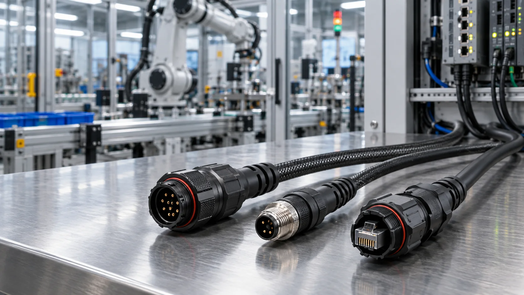
For wet or dusty equipment, evaluate the complete mated assembly. IEC 60529 defines IP Code classifications, but an IP rating should be tied to the exact configuration and test conditions. Ask whether the stated protection applies when mated, capped or panel mounted, and verify the cable jacket diameter and seal compression. Chemical exposure, UV, salt spray and repeated pressure washing require separate evidence; they are not automatically covered by an ingress rating.
Locking must suit the maintenance task. Threaded coupling can provide secure engagement, push-locking can reduce service time, and a sealed RJ45 format can preserve a familiar Ethernet interface. Keying and visible alignment features help prevent mismating. Leave enough clearance for the operator to grip and release the connector without pulling the cable. The industrial connector selection guide provides a broader framework for matching locking, ratings and environmental demands.
Design Length, Routing, and Bend Control
Cable length is an engineering input, not a purchasing afterthought. Excess length creates loops, increases installation time and can place the cable near noise sources. Insufficient length transfers tension to the termination and can prevent proper service access. Define the finished length from consistent datum points and state the tolerance, connector orientation and branch dimensions on the drawing.
Good data cable installation protects the cable from sharp edges, crushing and unsupported weight. Set a minimum bend radius for both installation and service, and give technicians enough room to reach the mating collar. Use clamps or guides that support the jacket without deforming pair geometry. A strain relief protects the termination, while routing supports manage the mass and movement of the entire run; one does not replace the other.
Large facilities may apply lessons from data center cabling, such as route labeling, separation, patch discipline and test records, but machine wiring adds vibration, oil, flexing and compact spaces. Document cable identifiers at both ends and avoid placing similar unkeyed interfaces on incompatible circuits. Model the routing in CAD, then verify it on a real build because access and bend behavior are difficult to judge from a drawing alone. Capture approved routes and support locations in work instructions so production units match the validated prototype.
Specify Moving and Flexing Applications
Continuous motion changes the cable design. A cable that is flexible during installation is not automatically rated for millions of repeated cycles. Robot dress packs, gantries, cable chains and rotating equipment can impose bending, torsion or combined motion. Define the motion type, bend radius, travel, acceleration, cycle rate and expected service life before choosing conductor stranding and jacket materials.
Control the neutral axis and prevent the cable from twisting unintentionally inside a carrier. Maintain the manufacturer's fill and spacing recommendations, and separate cables that can rub or generate heat. The connector should not absorb the carrier's mechanical load. Provide strain relief and a controlled transition from the moving section to the fixed termination.
Flex validation should reproduce the installed assembly, including connectors, overmolds, clamps and representative temperature. Monitor both conductor continuity and communication quality because a damaged shield or pair may degrade data before a conductor opens completely. When a cable is expected to be replaced as a service item, define a replacement route and mating procedure that do not disturb adjacent circuits.
For customized moving assemblies, provide JNICON with the machine motion profile, cable length, signal map and environmental conditions. The engineering review can then address conductor construction, jacket, shielding, connector exits and overmold geometry as one system rather than treating the cable and connector as independent items.
Validate Data Cable Assemblies Before Release
Qualification should test the link under realistic electrical and mechanical stress. A continuity check detects opens and shorts but does not prove high-speed performance. Depending on the protocol, validation may include wire-map verification, resistance, insulation tests, shield continuity, insertion loss, return loss, near-end crosstalk, packet-error monitoring or eye-pattern evaluation. The applicable limits must come from the approved system and interface specification.
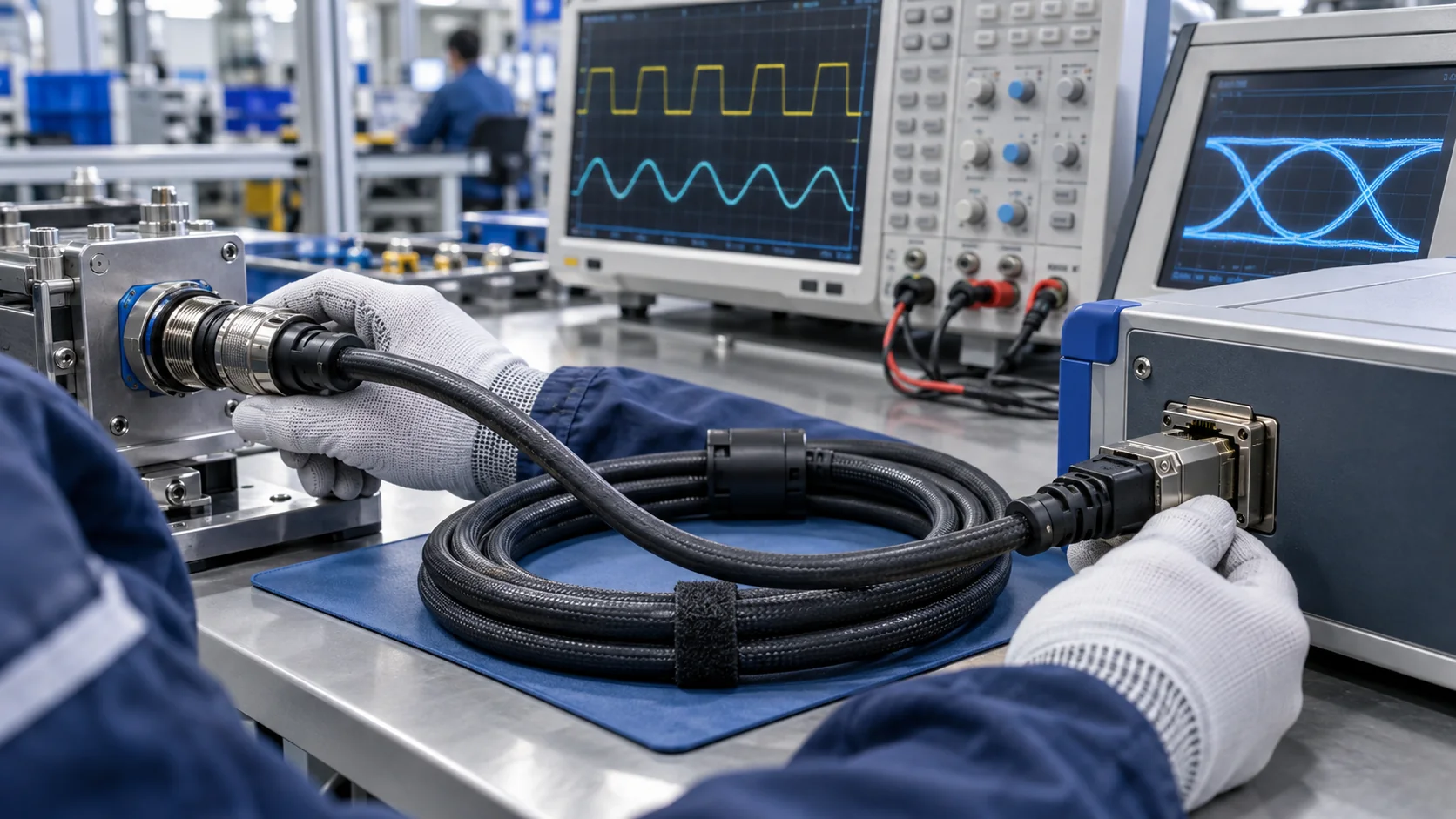
Test a representative length with the final connectors and assembly process. Add bulkheads, adapters and panel feedthroughs if they are part of the installed channel. Operate nearby motors, drives and switching loads while monitoring the communication link. Environmental testing may include vibration, temperature cycling, ingress exposure or cable flexing according to the equipment risk assessment.
Production testing should be proportional to the failure risk. Every custom assembly commonly receives pin-map and continuity verification; selected electrical or mechanical checks may be performed by qualification or sampling when justified. Record the test method, fixture revision and acceptance criteria so results are repeatable. A simple pass label without traceable limits offers little protection against process drift.
Change control matters after approval. New contacts, plating, cable material, shield construction, tooling or molding parameters can alter performance. Require notification and determine what must be revalidated. JNICON's custom cable assembly guide explains how drawings, samples and production controls work together.
Build a Production Drawing and Test Plan
A production drawing converts the engineering intent into measurable supplier requirements. Identify the connectors, contact gender, view orientation, pin map, cable construction, shield termination, finished length, branch points, labels, overmolds and tolerances. Reference controlled specifications rather than copying broad catalog claims. If the assembly has multiple similar branches, add durable identification and poka-yoke features.
The bill of materials should lock the approved connector and cable revisions or define an authorized-equivalent process. State which materials or performance characteristics cannot change without approval. Include packaging requirements that protect contact faces, prevent tight coiling and keep similar assemblies from being mixed during transport.
Create a test table with the characteristic, method, limit, sampling level and record requirement. Routine checks might include visual inspection, pin mapping, continuity, short-circuit detection and shield continuity. Project-specific validation can cover protocol performance, pull force, ingress, thermal behavior, vibration or flex life. Avoid vague instructions such as test cable or verify quality; they allow each operator to apply a different standard.
Link every shipped lot to its drawing revision and inspection result when traceability is required. A first-article report should confirm dimensions, materials, electrical map and key performance results before volume production. These controls help purchasing compare suppliers on the same technical scope and reduce the risk of an apparently equivalent cable creating field failures.
Compare Standard and Custom Data Cable Options
A standard assembly can shorten lead time when its connector, length, shielding and environment already match the equipment. It may also simplify replacement stock. However, forcing a catalog cable into an unsuitable route can create excess loops, adapter joints or uncontrolled strain. Compare total installed risk, not only unit price.
A custom data cable becomes useful when the project needs a special pin map, mixed power and signal contacts, defined branch lengths, a particular jacket, shielding treatment, labels or molded exits. Customization should solve a documented problem. Each special feature adds drawing, tooling, inspection and change-control needs, so the OEM should distinguish mandatory requirements from preferences.
For low-volume prototypes, a configurable field-attachable solution may support rapid iteration. For repeat production, factory-terminated or overmolded assemblies can reduce installation variation and simplify final equipment assembly. The correct choice depends on service strategy, annual volume, onsite skills, environmental exposure and validation cost.
Ask suppliers to quote samples and production quantities against the same specification. Compare documentation, engineering support, test coverage, lead time and change management in addition to price. A supplier that can explain the proposed conductor, shield and termination design is easier to qualify than one offering only a connector photo and a nominal cable length.
Select JNICON Components for OEM Projects
JNICON's Data & Signal Connectors category provides three practical starting points for industrial OEM projects. The M23 15-pin option combines higher-current and signal contacts for sensor and data applications. The M16 8-pin signal connector is positioned for sensor arrays and fieldbus systems. The M19 sealed RJ45 option supports industrial Ethernet connections where a familiar eight-contact data interface and environmental sealing are needed.
These catalog descriptions are screening information, not automatic approval for every protocol or installation. The OEM should confirm current, voltage, pin mapping, contact construction, cable diameter, shielding path, locking, ingress configuration and the latest product drawing. Where a standard connector does not fit the routing or cable requirements, JNICON can review a customized harness or molded assembly.
Choose by system function rather than shell size alone. A larger connector may provide space or current capability, while a compact interface may better fit sensor nodes. An RJ45-style interface can simplify Ethernet service, but a circular multi-pin design may be preferable when the architecture combines several signals or demands different locking. Samples should be evaluated in the actual enclosure with the intended cable route.
JNICON supports application review for industrial automation, rail transit and security equipment. Provide the real operating environment and validation expectations so the proposed components can be matched to the project rather than selected only from a web-page title.
Send an RFQ That Prevents Rework
A useful request for quotation gives every supplier the same technical target. Include the application, protocol, data rate, network topology, connector at each end, pin map, shield termination, cable construction, finished length, motion profile, temperature range, moisture or chemical exposure, annual volume and sample quantity. Attach mechanical drawings or enclosure models when connector clearance matters.
State the destination market and required documentation without assuming a component certificate automatically covers the completed machine. Ask for the exact product drawing, ratings, conditions of use, material declarations and test evidence relevant to the quoted configuration. If third-party approvals are mandatory, identify the standard and scope for the finished assembly.
Define acceptance before ordering samples. List the production tests, qualification tests, first-article documents, labeling and packaging. Explain which features are fixed and which may be proposed by the supplier. This encourages useful engineering alternatives while preventing silent substitutions that change the interface.
Finally, include the business forecast: prototype timing, ramp schedule, order quantities and service-spares plan. With these inputs, JNICON can assess a catalog connector, custom cable assembly or combined solution and quote a controlled scope. A complete RFQ shortens technical clarification, improves price comparison and gives engineering, quality and purchasing teams one basis for approval.
Related Products
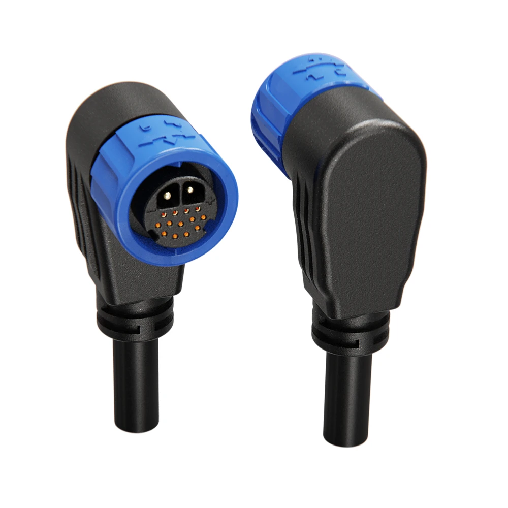
M23 15-Pin Signal Waterproof Connector 20A+5A Push Locking for Sensors & Data
15-pin high-density signal connector with 20A power and 5A signal contacts, push-locking and IP67-rated for sensor networks and data transmission.

M16 8Pin Signal Waterproof Connector 5A Screw Locking IP68 for Sensor Networks
5A 8 pin screw-locking waterproof signal connector with IP68 rating, field installable or molded with cable for sensor arrays and fieldbus systems.

M19 RJ45 Waterproof Connector 8Pin IP68 Screw Locking for Industrial Ethernet
8-pin RJ45 waterproof Ethernet connector with IP68 rating and screw locking for reliable industrial network connections in harsh environments.
Related Solutions

Industrial Automation
Empowering smart factory infrastructures with certified power, signal, and data connectors. Engineered to withstand continuous multi-axis robotic motion, eliminate electromagnetic interference (EMI), and ensure zero-downtime performance in harsh manufacturing environments.
Explore Solutions
Rail Transit
Empowering rolling stock, trackside signaling networks, and passenger information systems with certified heavy-duty power and signal connectors. Engineered to endure continuous dynamic vibrations, violent mechanical shocks, and extreme outdoor weathering.
Explore Solutions
Security & Safety
Empowering outdoor IP surveillance, smart access control, and emergency alarm infrastructures with certified, compact, weatherproof power and signal connectors. Engineered to guarantee zero signal dropouts and absolute data integrity in harsh environmental conditions.
Explore SolutionsFrequently Asked Questions
Conclusion: Specify the Whole Data Link
A dependable data cable is the result of coordinated protocol, conductor geometry, shielding, connectors, routing and validation. Factory OEMs reduce commissioning delays when they define the complete channel, test it under real machine conditions and control every production revision.
Send JNICON your interface drawing, protocol, cable length, environmental conditions and order plan through the inquiry and contact page. The team can review relevant data and signal connectors or a custom cable assembly for your equipment.


