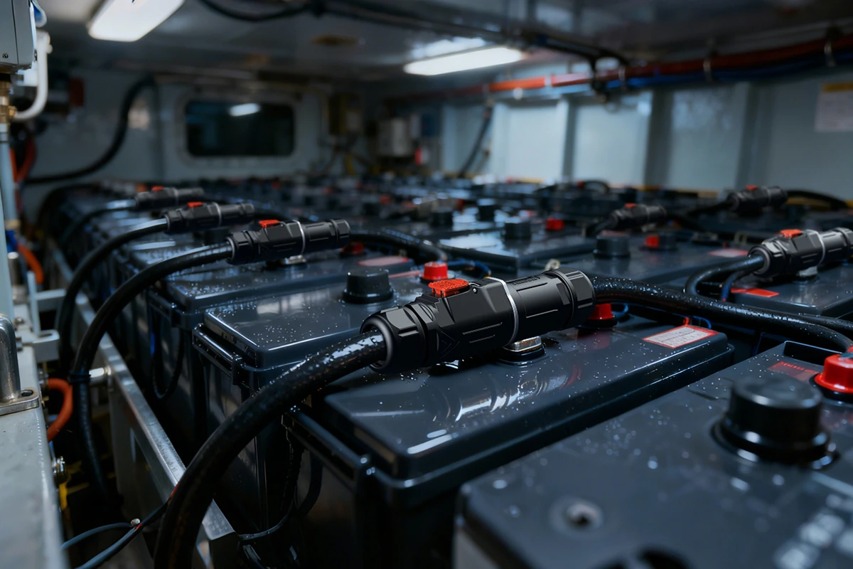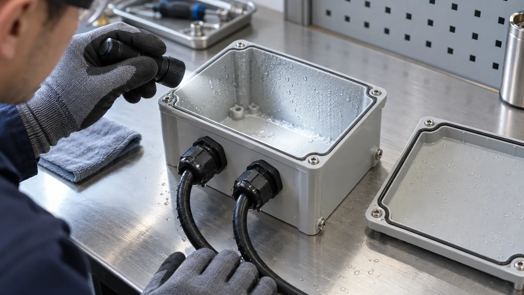
Ev charging connector selection inside a charger is different from choosing the handle that plugs into a vehicle. Charger OEMs need equipment-side power and signal interfaces that match electrical load, enclosure exposure, cable routing, assembly methods, and service intervals. This guide turns those requirements into a practical specification and validation plan.
Define the Interface Before Choosing a Connector
The phrase ev charging connector can describe several interfaces. A driver usually means the external vehicle coupler. A charger engineer may mean a removable connection between a power module and distribution assembly, a cabinet-to-cable interface, a control harness connection, or a serviceable connection within an energy-storage-assisted charger. Those are different design problems. A connector suitable for a protected control compartment is not automatically suitable for a wet cable-entry point or a high-current output path.
Start an interface schedule before asking suppliers for a part number. List each mating pair, its location, whether it is exposed when the enclosure is open, and whether it must be disconnected during routine maintenance. Identify which side is fixed, which side moves, and who assembles each half. Mark whether the circuit carries continuous power, intermittent power, protective earth, auxiliary power, sensing, or communication. Record whether an operator could accidentally mate it under load.
The industry standards for the vehicle-facing coupler should not be confused with an internal equipment connector. The IEC 62196 family addresses EV plugs, socket-outlets, vehicle connectors, and inlets; SAE J3400 addresses a vehicle charging coupler. A generic circular industrial connector does not become a compliant vehicle coupler because it is installed inside charging equipment. Specify those interfaces separately and obtain the relevant compliance evidence for the complete charger.
Translate Charger Load Into Electrical Ratings
The headline current on a connector catalog page is a starting point, not a complete equipment rating. Compare the charger duty cycle, ambient temperature, conductor size, pin count, contact plating, termination, and enclosure ventilation with the manufacturer's test conditions. If several circuits operate at once, ask whether the published current applies to one energized contact or to the populated connector at the intended temperature. Clarify whether the current is continuous and what temperature-rise limit the design uses.
Voltage selection also needs more than a nominal number. Document the operating range, transient environment, system grounding, insulation requirements, and the separation required between power and lower-voltage circuits. Confirm both operating and withstand-voltage data for the exact configuration being quoted. A high-current connector can still be unsuitable if creepage, clearance, or cable insulation does not match the assembly design.
Build a load table with normal current, peak current and duration, maximum operating voltage, expected ambient at the connector, and allowable conductor temperature. If the charger can derate or fault, include those cases in the test plan. Ask the supplier for a temperature-rise curve or test report at the proposed cable gauge and termination. Do not assume a current rating printed for a different pin arrangement, cable size, or mating state will transfer to your BOM.
Separate Power, Control, and Communication Paths
Charger cabinets often combine bulky conductors with smaller control and sensing wires. A single hybrid connector can reduce interfaces and simplify installation, but it also concentrates design constraints. A separate power connector and signal connector may make thermal management, field replacement, and troubleshooting clearer. Choose the architecture around service and fault containment, not only panel space.
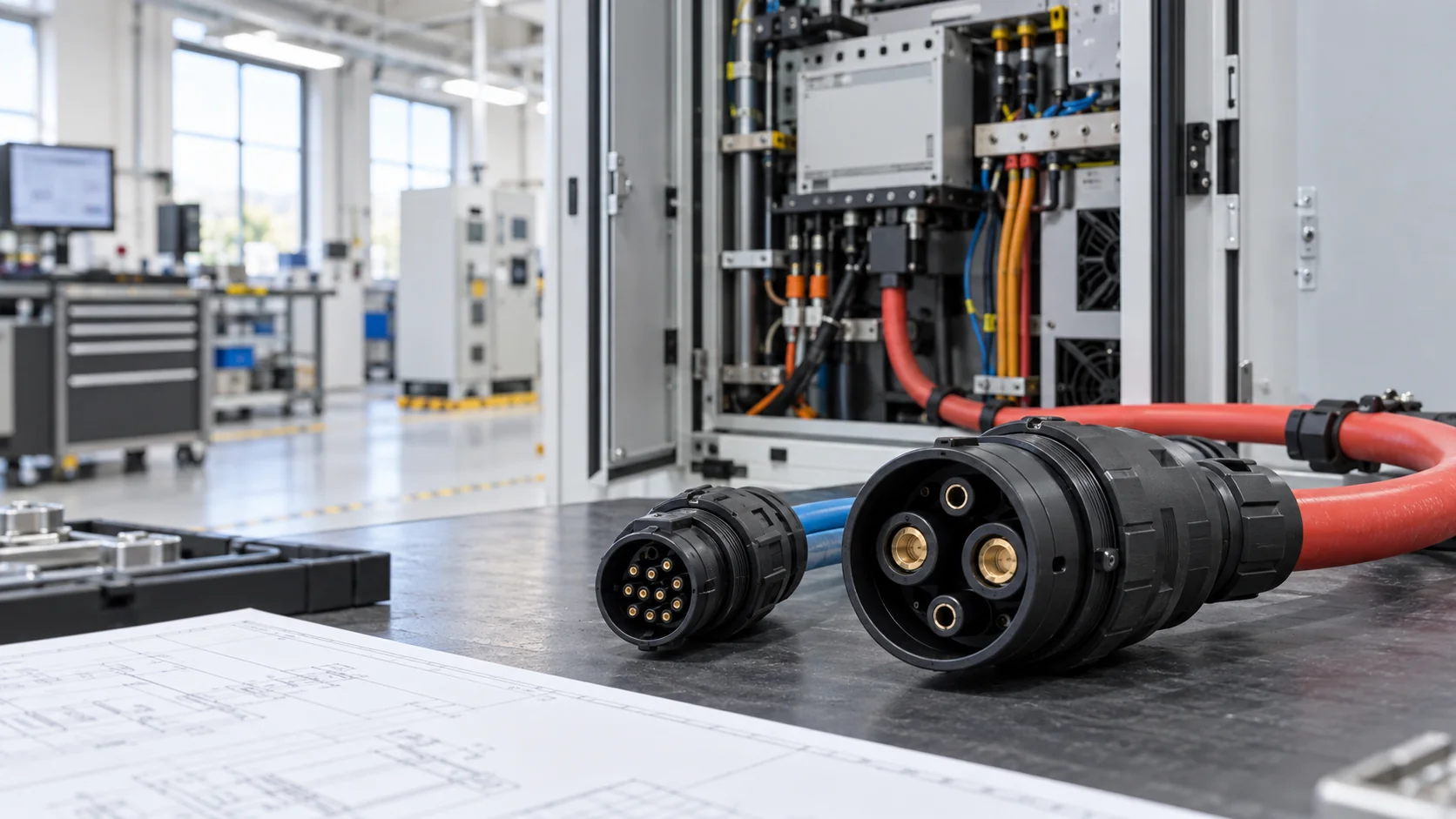
For a hybrid design, identify which contacts carry power, which carry low-level signals, and whether the pin assignment prevents miswiring. Consider the effect of switching noise, proximity to contactors, and shared cable shields. Provide the supplier with the pin map, not only a phrase such as “power and signal.” Include whether the signal pair requires twisting or shielding and where the shield terminates. If the cable runs to a controller, test the assembly in its installed routing rather than assuming a connector-level test proves communication quality.
Where maintainers must replace a charger module, a keyed, clearly labeled interface can shorten work without creating a dangerous opportunity to interchange harnesses. The system design must still manage de-energization and interlocks. A connector's locking method is not a substitute for safe electrical isolation.
Control Contact Resistance and Temperature Rise
Heat at a charging connection is the combined result of current, contact resistance, termination resistance, and nearby thermal conditions. A small rise in resistance can have a large effect at high current. Engineers should therefore look beyond the advertised ampere value and request evidence on contact design, plating, termination repeatability, and thermal performance after cycling or vibration.
Measure the completed connection, not only an unmated contact sample. A useful validation setup places temperature sensors near the mated interface and at the cable termination under the intended current and ambient. Compare the connection's stabilized temperature with the conductor, enclosure, and adjacent component limits. Repeat after mating cycles and environmental exposure where the service profile warrants it. Document the test current, conductor cross-section, cable length, airflow, and acceptance criterion so another engineer can reproduce the result.
JNICON's high current connector design guide covers broader industrial load selection, while this guide focuses on charger equipment interfaces and the service conditions around them. An OEM should still confirm final limits against the exact connector drawing and its own charger safety assessment; a generic catalog rating is not an approval for every cabinet layout.
Specify Cable Gauge, Termination, and Strain Relief
The cable is part of the connector system. Select conductor size using the electrical design and installation rules, then verify that the chosen contact and backshell actually accept that conductor and insulation diameter. A terminal may fit the copper cross-section yet reject the cable jacket, or the gland may seal only over a narrower diameter range. Both details belong in the RFQ.
Ask whether the production termination is crimped, soldered, or otherwise assembled. For crimped contacts, define approved tooling, strip length, crimp height or pull-force checks, and inspection criteria. For pre-molded cable assemblies, clarify overmold material, bend radius, transition geometry, and how the supplier controls insert positioning. A good electrical joint can still fail early if cable movement concentrates at the exit.
Document the routing path inside the charger. Leave a service loop where modules may be removed, but avoid loose cable that rubs a door hinge or cooling fan. Clamp the harness so a technician's pull load does not transfer to the contact. Where the cable enters a weather-exposed enclosure, verify sealing on the final cable outer diameter and the actual panel thickness. Review the assembled cable with the supplier during prototype build, not after all cabinet tooling is frozen.
Match Sealing to the Real Exposure Point
An IP rating applies to a tested configuration under defined conditions. It does not mean every installation using that connector remains sealed. Panel cutout, gasket compression, mating state, cable diameter, end-cap use, and assembly technique all affect the completed system. In charger equipment, rain splash, dust, condensation, washdown, road salt, and thermal cycling may appear in different combinations depending on placement.
Place the connector on the interface map and describe its exposure. Is it inside a protected cabinet, on an exterior wall, or at an access door opened outdoors? Will it spend any time unmated during service? Does water collect below the cable gland? Select the sealing approach around that condition. A connector rated IP67 when fully mated may need a separate cap when unmated, and its seal may need reinspection after repeated opening.
Use the enclosure's complete ingress-protection test and the applicable product documentation to verify the design. Do not infer a whole-charger rating from a single connector's claim. If an enclosure needs pressure equalization, drain strategy, or condensation control, solve that at system level. For related failure analysis, see JNICON's waterproof-connector condensation and leakage guide.
Choose a Locking Method for Assembly and Service
Bayonet and quick-lock styles can reduce time spent mating interfaces in a production line, but the fastest connection is not automatically the best one. Define the available hand clearance, visibility, required tool access, and risk of partial mating. Where vibration or routine servicing is expected, ask how the design confirms full engagement and how the lock resists accidental release.
Consider who handles the interface. A factory technician can use a fixture and visual checklist; a field service technician may work with gloves inside a crowded cabinet. A connector that appears easy on a bench can be difficult to align at the back of a module. Prototype the installation sequence with realistic cable lengths and neighboring hardware. Check whether the keying prevents cross-mating between similar power and control cables.
Specify a maintenance procedure that starts with isolation and verification of a de-energized state. Do not use the ability to disconnect quickly as permission to break load. If frequent service is part of the requirement, include mating-cycle durability and post-cycle contact-resistance checks. The supplier should state when a seal, contact, or entire assembly should be replaced rather than simply reconnected.
Evaluate Signal Integrity and EMC at System Level
Power converters, contactors, and high-current cables produce an electrically noisy setting for control wiring. The ev charging connector used for control or monitoring should preserve the intended shielding, grounding, and conductor geometry of the harness. A metal shell, a shielded cable, or a twisted pair is only one component of a system-level EMC design.
Before selecting a hybrid interface, draw the signal path and return path. Identify low-level analog sensors, digital I/O, Ethernet or other communications, and any isolation boundaries. Confirm whether the selected contacts and layout support the bandwidth, impedance, and noise margin the circuit needs. Avoid placing a sensitive signal against a high-current path without assessing coupling and routing. If the connector includes a shield termination, define exactly where the shield bonds in the assembly.
Verify communication in the assembled charger under representative switching, charging, standby, and fault transitions. Continuity alone will not reveal intermittent packet errors or common-mode noise. Ask the supplier to provide pin numbering, orientation views, and harness test definitions that agree with the OEM drawing. For more detail on harness documentation and validation, JNICON's cable assembly guide is a useful companion.
Build Traceability Into Charger Harness Production
Charger OEMs often revise cabinet layouts as power modules, controllers, or market requirements change. A connector purchase should therefore be tied to a controlled drawing and bill of materials. Record the connector family, pin count, contact material and plating, cable type, wire gauge, cavity map, backshell or gland, gasket, and labeling. State the revision level on both the drawing and purchase order.
For an assembled harness, define the checks that happen at production release: visual inspection, pin-position verification, continuity, insulation tests where appropriate, and functional tests for signals that need more than point-to-point wiring. Capture failed-test disposition and rework rules. A sample that passes once does not prove repeatability across batches; a process control plan should show how tooling, operators, and inspection stay consistent.
Ask the supplier how it manages engineering changes. A substitute cable jacket or contact plating can alter seal fit, crimp settings, and long-term resistance. Require approval before substitution and retain the material and test evidence needed for your market and customer. JNICON can review application drawings and sample assemblies with OEM teams, but final qualification should be based on the actual cabinet design and agreed test plan.
Validate the Assembly Under Charger Operating Conditions
A useful validation plan moves from component checks to a complete charger installation. Begin with drawing and dimensional review, then verify mating force, correct keying, retention, contact resistance, and cable pull or strain-relief performance as applicable. Test the connector in the same mounting orientation, panel thickness, and cable routing planned for production. If the cabinet is exposed outdoors, include the relevant ingress and temperature-cycling conditions.
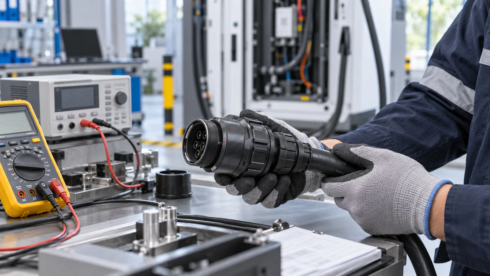
Next run energized tests at representative continuous load and specified peaks, logging contact and termination temperatures. Where vibration or repeated module changes are expected, repeat electrical checks after those mechanical exposures. For a signal interface, evaluate communications while the power stage switches. Record baseline and post-test results rather than only a pass/fail label; trends can show a marginal design before an outright failure.
Qualification must also cover the charger as a system. IEC 61851-1 describes general requirements for EV supply equipment, while vehicle-facing connector standards address a different interface. Neither reference by itself certifies an equipment-side connector or completed charger. Use the current applicable edition, local requirements, and the OEM's certification plan. Ask your component supplier for relevant test data, but keep compliance ownership with the equipment manufacturer.
Compare Three Practical JNICON Interface Options
JNICON's catalog provides several starting points for a charger equipment discussion. The M40 4-pin 120A bayonet-lock connector is presented for EV charging and power applications. The MJ32 2-pin 120A quick-lock connector offers a different pin count and locking approach for an equipment-side power path. For a combined power-and-control requirement, the M40 2+4-pin hybrid connector is a family to evaluate, subject to confirming its exact configuration and ratings.
These examples are not interchangeable drop-in approvals. A 2-pin power connection cannot replace a 4-pin interface without reworking the circuit design. A hybrid assembly adds signal-routing and service considerations. Compare the supplier drawing, mating half, panel cutout, cable range, environmental rating, and test conditions against your application. If a connector needs custom pin assignment or a finished cable assembly, send the configuration as a drawing, not only a product-page link.
JNICON's broader new-energy and industrial-automation solution pages can help buyers understand the adjacent product families. For a specific charger, the engineering review still has to identify the exact electrical path and mechanical constraints before selecting a model.
Send an RFQ That Engineers Can Actually Answer
A useful RFQ reduces guesswork for both the charger OEM and the connector supplier. Include a system block diagram identifying the interface, photographs or CAD views of the mounting location, the connector's role, the mating and unmated conditions, and the planned build volume. Add the voltage and current table, ambient temperature at the interface, cable construction, pin map, shield requirements, panel thickness, available space, and required service cycles.
State whether you need loose connectors or a finished harness, the test evidence you expect, and the standards that apply to your equipment. Distinguish mandatory requirements from preferences. If you request IP67, say whether that is required mated only or during service as well. If a certificate matters, identify the exact part and market scope to avoid confusing a factory management certificate with approval of the connector configuration.
Ask for a drawing review and sample plan before setting a production schedule. A supplier should be able to flag a cable-diameter mismatch, unclear pin map, or unrealistic bend clearance early. Document any agreed changes so the prototype, qualification sample, and production BOM remain aligned. This disciplined handoff is often more valuable than choosing a connector by catalog current alone.
Related Products
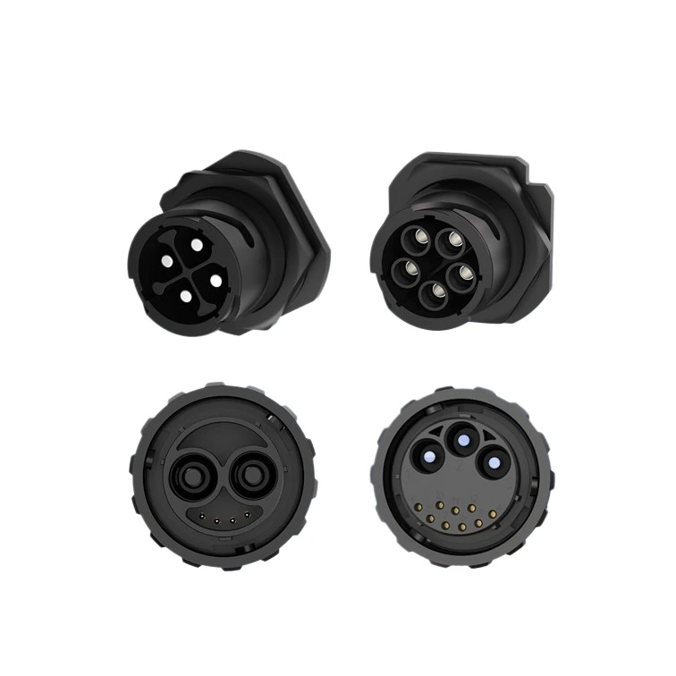
M40 4-Pin Waterproof Connector 120A Bayonet Lock for EV Charging
120A bayonet lock waterproof connector for EV charging and energy storage, with IP67 protection and reliable power transmission.
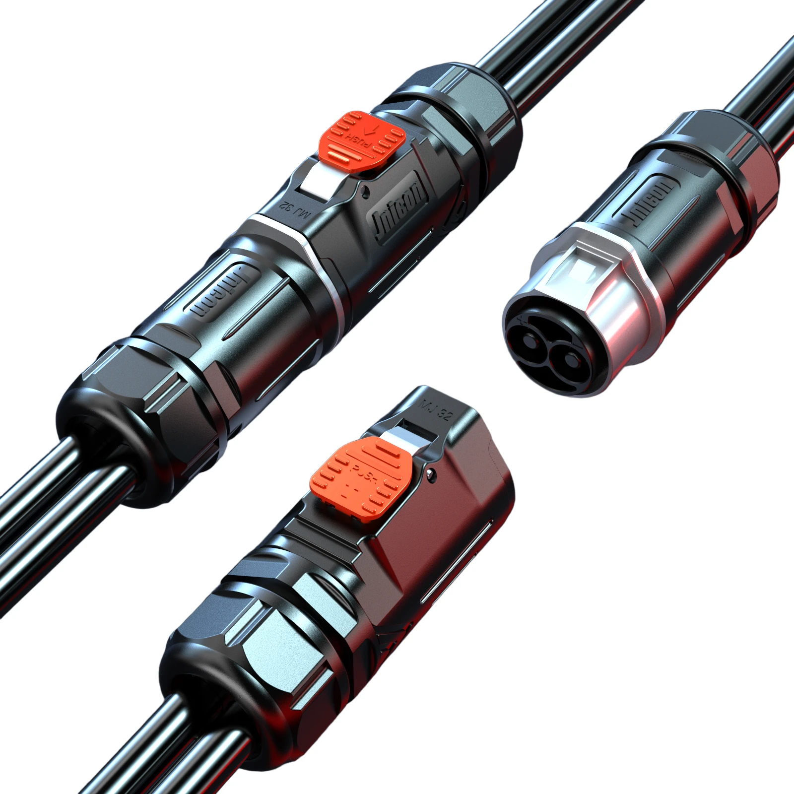
MJ32 2-Pin Waterproof Connector 120A Quick Lock for EV Charging
120A quick-lock waterproof connector for EV charging and energy storage, with IP67 protection and silver-plated contacts.
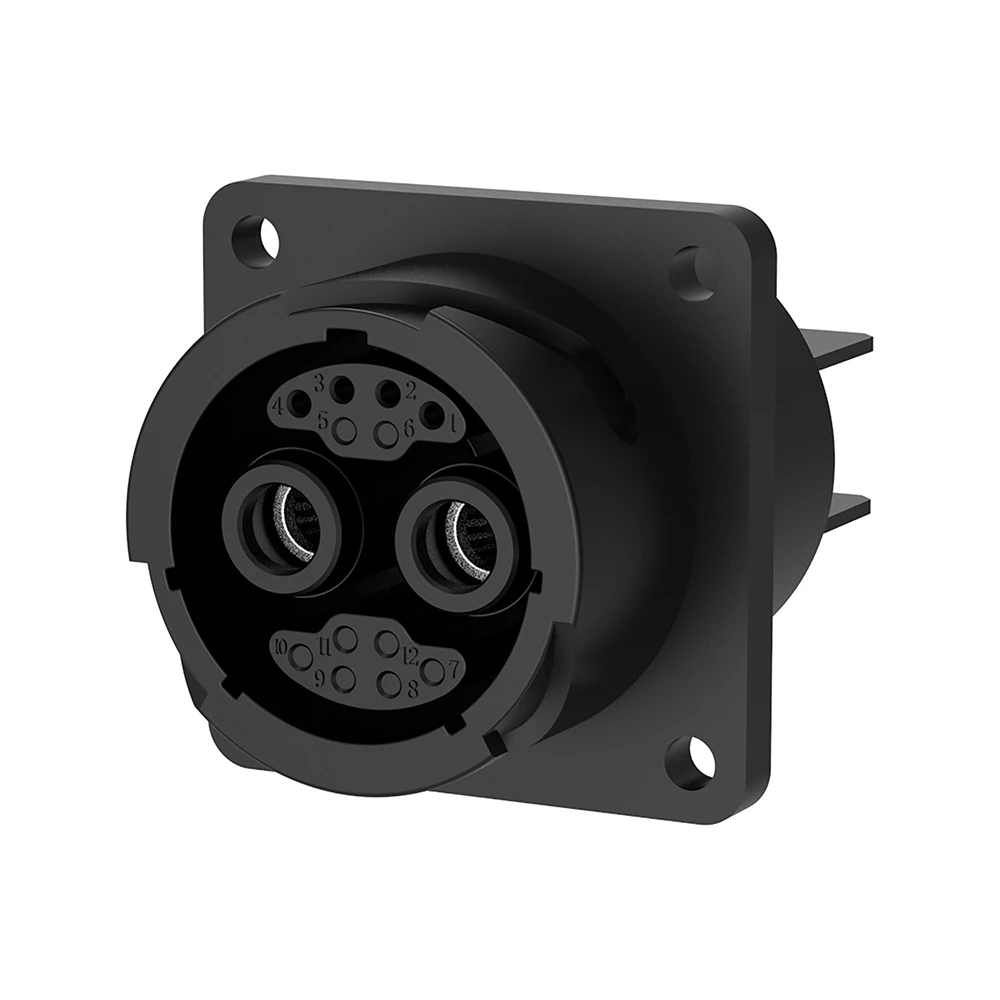
M40 2+4 Pin Hybrid Waterproof Connector for Power and Signal
120A+10A hybrid bayonet lock waterproof connector combining power and signal in one compact design.
Related Solutions

New Energy & Energy Storage
Safeguarding high-capacity grid infrastructures with certified high current connectors engineered to withstand massive voltage loads, minimize thermal buildup, and eliminate systemic arcing risks from cell to grid container.
Explore Solutions
Industrial Automation
Empowering smart factory infrastructures with certified power, signal, and data connectors. Engineered to withstand continuous multi-axis robotic motion, eliminate electromagnetic interference (EMI), and ensure zero-downtime performance in harsh manufacturing environments.
Explore Solutions
Solar & Photovoltaic
Engineered for 1500V DC utility-scale solar farms and smart PV tracking systems. Our TUV/UL certified connectors eliminate DC arcing risks and withstand persistent UV degradation and sandstorms in desert environments.
Explore SolutionsFrequently Asked Questions
Conclusion: Specify the Whole Charger Interface
Selecting an ev charging connector for an OEM charger means defining the circuit, cable, mounting point, environment, production process, and test evidence together. JNICON’s equipment-side power, hybrid, and custom assembly options can provide starting points, but the correct choice depends on the exact charger design.
Send your drawings, load profile, and installation constraints through the JNICON inquiry page to request a technical review and quotation.