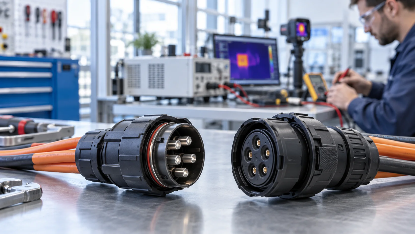
Energy storage connectors need a defined conductor interface as well as an electrical rating. This OEM guide compares cable and busbar arrangements through installation space, alignment, assembly controls, replacement access, and quotation scope so engineering and purchasing teams can approve the same configuration.
Define the Interface Before Comparing Cable and Busbar
Energy storage connectors should be compared at a defined interface: battery module to rack, rack to distribution, or distribution to conversion equipment. A cable termination and a busbar termination describe how conductors join an interface. Either architecture can include a separable connector, and a busbar can also use a bolted joint. Record both the conductor arrangement and the connection method.
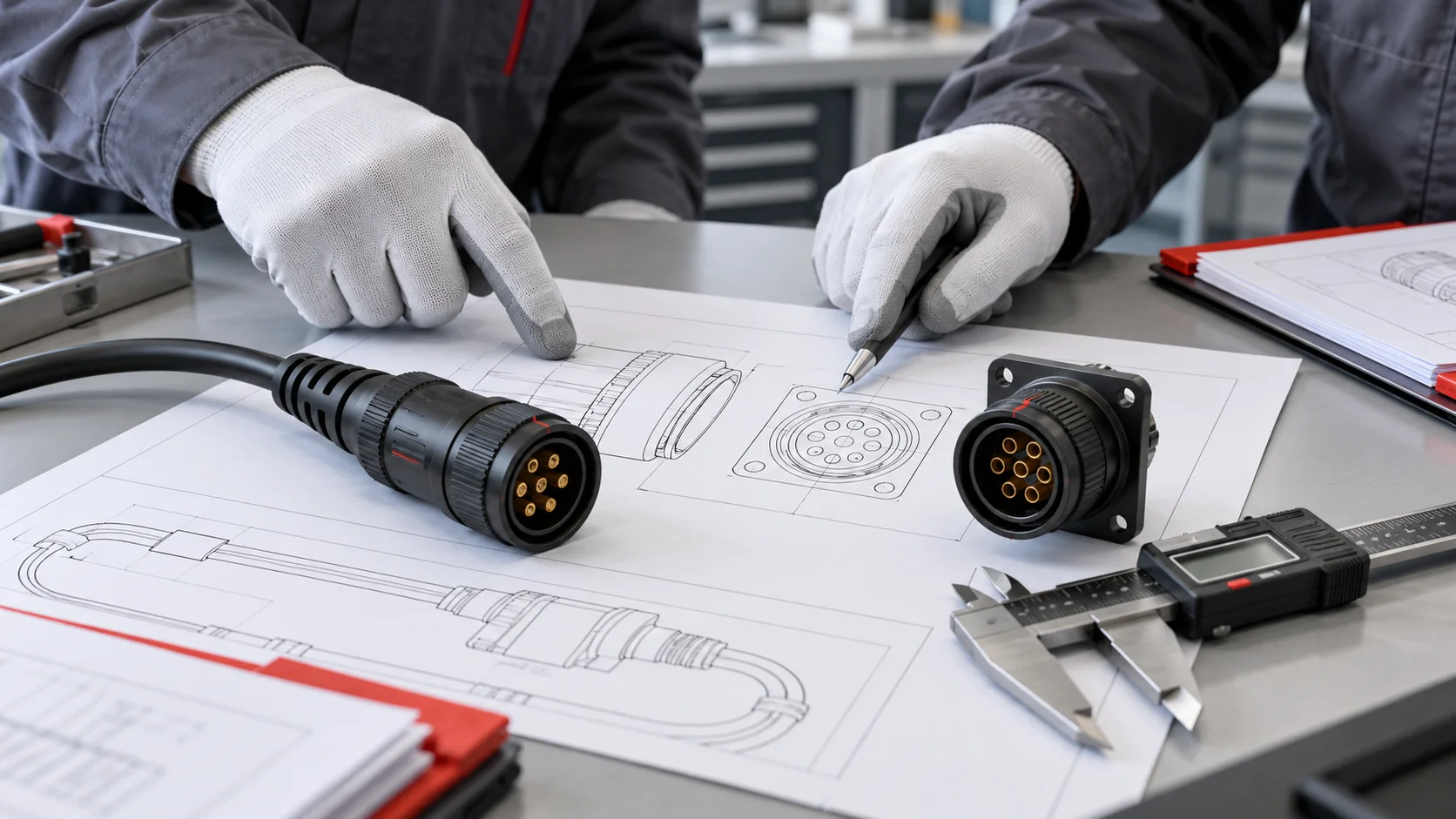
Start with a simple interface drawing. Mark the fixed and removable assemblies, positive and negative circuits, protective barriers, and the direction in which parts are installed. Show the connector's two halves and the conductor attached to each. This prevents a purchasing comparison between a complete cable assembly and a receptacle that still needs its busbar, hardware, and insulation.
Phoenix Contact's energy storage connector overview presents battery-pole and busbar connection approaches, including front and rear connection arrangements. These are useful architecture categories, not evidence that different manufacturers' products are interchangeable. The following review questions are a design checklist rather than a product qualification standard.
For broader application context, see the battery energy network connector guide. Here the decision concerns the physical power interface and the evidence needed to release it.
Compare the Two Architectures Against the Same Requirements
A useful comparison holds the operating requirements constant. Define the current profile, maximum working voltage, ambient conditions, enclosure arrangement, and service procedure before selecting an architecture. Otherwise a compact busbar concept may be compared with an oversized cable harness, or a cable assembly may appear cheaper because the comparison excludes its supports and termination work.
| Review item | Cable-based interface | Busbar-based interface |
|---|---|---|
| Routing | Can follow a shaped route within the cable's permitted bend limits | Requires controlled geometry and support positions |
| Dimensional variation | Needs defined slack, retention, and strain relief | Needs an explicit alignment and tolerance review |
| Assembly evidence | Cable, contact, tooling, and termination records | Bar dimensions, finish, joint or connector, and support records |
| Service access | Space to release the latch and move the cable assembly | Space for withdrawal or access to the specified joint |
| Commercial scope | Include harness fabrication and routing hardware | Include fabrication, insulation, supports, and mating hardware |
Use this table to identify missing inputs, not to award a universal winner. Cable assemblies and busbars can coexist in the same cabinet. For example, a fixed distribution section may use bars while a removable subassembly connects through a supported cable. Approve each boundary on its own requirements.
Reserve Space for Cable Routing and Disconnection
A cable-based layout needs space for the conductor, insulation, connector body, locking mechanism, and the movement required for servicing. Draw the complete installed envelope rather than only the panel cutout. The shortest cable on a drawing may pull against a termination once the enclosure and module positions reach their permitted limits.
Use the exact cable manufacturer's bend guidance for installation and any intended movement. Review the first bend behind the connector, nearby clamps, sharp edges, abrasion points, and access to the latch. Strain relief should manage the expected cable loads without using the electrical contact as a mechanical support. A larger conductor can also change the cable stiffness and the available service route.
Check the replacement sequence on a de-energized mockup. Can the technician reach the release feature with adjacent assemblies installed? Can the disconnected cable be secured away from other interfaces? Does its removal require disturbing an unrelated circuit? Record these observations before freezing the harness length and connector exit orientation.
Do not assume that flexible routing permits arbitrary repeated movement. If a module or door moves during normal operation, specify the movement and qualify the cable assembly for that duty. Installation flexibility and continuous-flex performance are separate requirements.
Control Busbar Geometry, Finish, and Mechanical Support
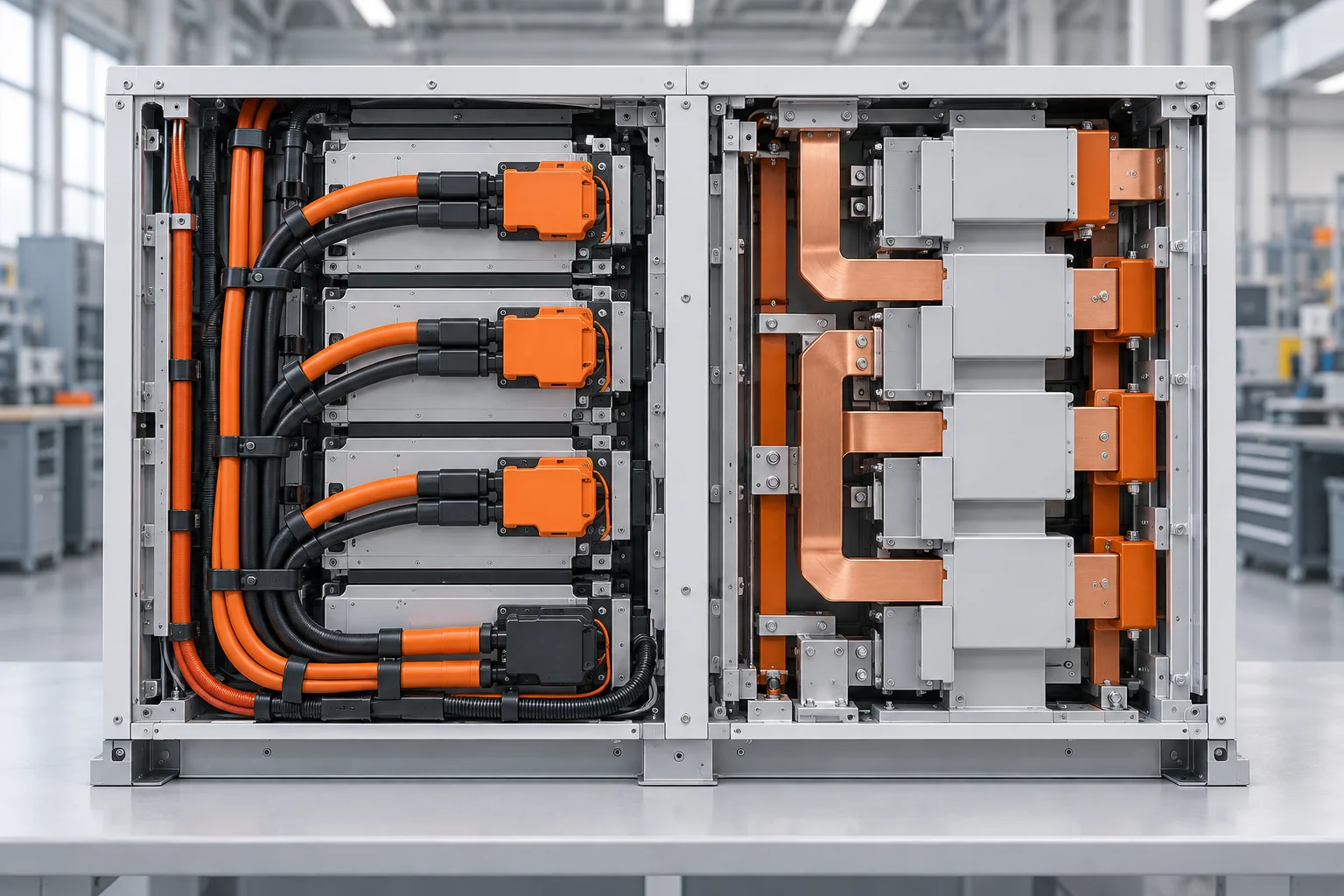
A busbar-based interface depends on more than a nominal bar cross-section. The approved drawing should identify material, dimensions, surface finish, insulation boundaries, support positions, and the mating feature. A separable busbar connector also needs its own permitted blade geometry, insertion depth, and alignment conditions.
TE Connectivity's busbar connectivity guide treats busbar size, shape, material, plating, insulation, and the connector as linked selection considerations. Its product examples use defined mating dimensions. Use that principle to request a controlled interface drawing; do not transfer a TE model's dimensions or ratings to a JNICON part.
Separate conductor support from electrical engagement. Review how the bar is restrained during assembly, transport, and operation. A connector must not be assumed to carry the weight or alignment loads of a distribution assembly unless its documented design allows that duty. Thermal expansion and cabinet movement also belong in the mechanical review.
For a bolted termination, obtain the specified hardware stack and assembly procedure from the responsible manufacturer. For a pluggable termination, obtain the approved mating pair and insertion requirements. Treat these as different assembly processes with different inspection records, even when both connect to the same busbar.
Keep Current Ratings and Thermal Evidence Configuration-Specific
The stated current rating is only a starting point for an interface review. Ask which conductor size, termination, ambient conditions, and test arrangement support the proposed configuration. A catalog family can contain several variants. The number in a product title does not establish acceptable performance for every cable, busbar, enclosure, or operating cycle.
For both architectures, review the entire conductive path, including terminations and joints. Conductor resistance, contact resistance, enclosure cooling, nearby heat sources, and assembly quality all affect the result. A larger bar does not correct a poorly controlled interface, and a larger cable does not remove a termination problem.
Write the required evidence into the sample plan. Identify the actual configuration, current profile, measurement positions, relevant thermal limits, and the conditions under which results will be accepted. The equipment designer and qualification team should set those criteria for the application. This article does not prescribe test voltages, current margins, or acceptance temperatures.
The high-current connector thermal review checklist covers the separate task of investigating a hot interface. Use it after identifying the exact build, rather than substituting a generic thermal claim for the cable-versus-busbar comparison.
Review Alignment and Tolerance Before Freezing the Cabinet
Every interface needs a tolerance review, but cable and busbar arrangements distribute variation differently. A cable can accommodate some positional change through its approved route. A rigid bar carries dimensional variation into its supports and mating features. Neither arrangement should be forced into place to compensate for an unresolved stack-up.
List the features that locate each half: panel, bracket, module rail, connector flange, bar bend, and conductor attachment. Identify the datum and allowed variation for each. Review the most restrictive combination, including angular error and withdrawal direction. A floating mount or blind-mate capability must be supported by the exact connector's documentation, not inferred from appearance.
On a de-energized assembly, confirm that the intended mating sequence works without prying, bending a terminal, or drawing misaligned parts together with fastening hardware. Check that the latch can reach its final position and that the conductor supports can be installed without shifting the interface.
Keep the reviewed arrangement in the controlled drawing set. If a later cabinet revision moves a support or changes a module supplier, revisit the stack-up. An electrical part number that remains unchanged does not prove that the new mechanical installation is equivalent.
Separate Polarity, Insulation, and Service Safety Requirements
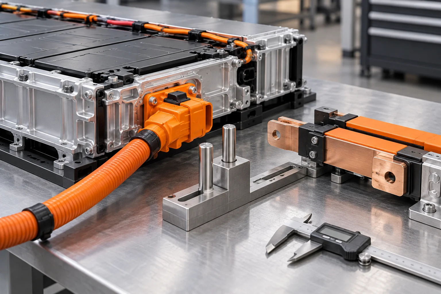
Connector color, mechanical coding, insulation, and the equipment's isolation procedure address different risks. Record polarity on the wiring and interface drawings. Confirm the permitted mating combinations and the identification method for replacements. A color difference alone does not prove that an incorrect connection is mechanically prevented.
Review the condition of the interface when mated, unmated, during assembly, and during the approved service sequence. Specify the required barriers and protective measures for each condition. A sealing claim does not establish touch protection, insulation coordination, or suitability for interruption under load. Those requirements need their own model-specific evidence.
In particular, do not assume that a quick-disconnect connector is a load-break device or that a removable module is hot-swappable. Qualified personnel must use the equipment's approved isolation and verification procedures. Where disconnection under load is required by the design, select a device explicitly documented and qualified for that function.
For a busbar arrangement, include insulation edges, support geometry, and access through openings in the review. For a cable arrangement, include abrasion protection and the location of disconnected ends. Keep these requirements visible in the acceptance plan rather than reducing safety to a single connector feature.
Specify Cable Termination and Busbar Assembly Controls
Production approval should describe how the connection is made consistently. For a crimped cable assembly, obtain the approved cable and contact combination, preparation requirements, tooling identification, and inspection criteria. The responsible supplier should define applicable process checks and traceability. Do not borrow a crimp setting from a visually similar contact.
For a busbar termination, identify whether the joint is bolted, clamped, welded, or connected through a separable contact. Record the applicable preparation, hardware, assembly procedure, and inspection requirements. Surface damage, contamination, and a changed finish should be reviewed against the approved process instead of accepted because the parts still fit.
Define which operations occur at the component supplier, harness supplier, cabinet factory, and installation site. A quotation for an unfinished termination can shift work and responsibility downstream. The purchase order should identify the supplied state and the documents required to complete the assembly.
Retain the production reference sample with its drawing revision and component list. A signed sample without configuration records is difficult to reproduce. Include a change-control rule so that a different cable source, contact finish, busbar geometry, or assembly tool triggers the appropriate engineering review before shipment.
Design the Replacement Sequence Before Choosing the Interface
Serviceability depends on the whole replacement operation. Define the unit that will be replaced: cable, connector half, module, or complete distribution section. Then review access, isolation, conductor restraint, spare parts, and the inspections required before return to service. A connector that separates easily may still be inaccessible behind another assembly.
For cable-based connections, check whether the replacement harness can follow the approved route without removing unrelated hardware. Confirm that the replacement has the correct length, conductor construction, connector orientation, and markings. For busbar-based connections, check the removal direction, access to supports, and whether adjacent bars or barriers must be disturbed.
Define the expected handling and mating duty in the requirement. Request evidence for the selected part and conditions rather than using a generic lifetime statement. If the planned service sequence changes the alignment or loading conditions, include those conditions in the sample review.
Document the post-replacement checks and the responsible role. Keep procedures tied to the equipment's approved service instructions. The objective is a repeatable maintenance process, not the shortest possible unplugging motion or an unsupported claim that one architecture eliminates maintenance.
Compare the Complete Delivered Cost, Not Only Connector Prices
Compare quotations against the same boundary and supplied state. A cable assembly quotation may include cut length, contacts, protective sleeving, labels, testing, and packaging. A busbar quotation may exclude insulation, supports, fastening hardware, or the connector that makes the bar removable. Missing scope can reverse an apparent unit-price advantage.
Build a short comparison with component cost, fabrication work, assembly operations, inspection, tooling, and replacement scope. Keep one-time engineering or tooling charges separate from recurring unit prices. Ask suppliers to identify minimum order quantities, drawing assumptions, sample deliverables, and any items the buyer must provide.
Do not assume savings without a controlled build comparison. Time an assembly trial only when both configurations use approved processes and comparable inspection coverage. A faster prototype assembled without required checks is not evidence of lower production cost. Record any unresolved steps so procurement does not treat an incomplete estimate as an agreed production price.
For sourcing discipline, use the connector manufacturer RFQ and sample checklist. Attach the interface drawing to the inquiry so suppliers can quote a defined cable or busbar configuration instead of interpreting a broad request for “BESS connectors.”
Use a Configuration-Based Sample Acceptance Plan
A sample review should close specific questions before production release. Identify the exact part numbers, mating halves, conductor details, insulation, supports, and drawing revisions. Record whether the sample represents the intended production process or a prototype process with known differences.
- Identity: match the received parts and supplied documents to the proposed bill of materials.
- Fit: inspect the installation envelope, alignment, support positions, and release access on a de-energized mockup.
- Assembly: verify that termination and inspection instructions cover the delivered configuration.
- Performance evidence: review the agreed electrical, thermal, environmental, and mechanical qualification records for applicability.
- Release: name the reviewer, accepted configuration, open actions, and conditions for production approval.
Keep an open item open when evidence is missing. A successful dimensional fit does not establish current capacity, and a component test does not automatically qualify the assembled cabinet. Any additional energized or high-voltage testing belongs with qualified personnel under an approved plan.
If a supplier proposes a substitute during sampling, update the comparison and document the change. Do not let a trial part silently become the approved production interface merely because the original delivery schedule was tight.
Send JNICON an Interface Brief That Can Be Quoted
An actionable inquiry includes the circuit role, current profile, working voltage, environment, and the cabinet or module drawing. Add the available installation envelope, conductor route or busbar drawing, service direction, expected handling duty, and the acceptance documents required. State which information is fixed and which remains open for engineering discussion.
JNICON's 200A energy storage connector page lists crimp and busbar termination options. The related product cards below provide additional catalog starting points. These are candidates for review, not an approval of a current rating or direct interchangeability in your equipment. Request the exact configuration drawing and applicable evidence before selection.
Ask for a response that identifies the proposed mating pair, conductor or bar interface, supplied state, sample scope, and outstanding technical questions. A clear response should distinguish a standard option from a custom change. Confirm the commercial scope only after engineering has identified what will actually be supplied.
The practical outcome is a controlled interface decision: cable, busbar, or a combination, supported by the installation drawing, production process, and sample acceptance record. Keep the reason for that choice alongside the approved configuration so future revisions can be evaluated against the same requirements.
Related Energy Storage Connector Options

200A Energy Storage Connector DC1000V IP67 Crimp & Busbar for High-Power ESS
200A/1000V DC high-current energy storage connector with IP67 protection, available in crimp and busbar termination options for high-power BESS and utility-scale solar inverters.

150A Energy Storage Connector DC1000V IP67 Crimp & Busbar for Commercial ESS
150A/1000V DC energy storage connector with IP67 protection, available in crimp and busbar termination options for commercial and utility-scale battery energy storage systems.

120A Energy Storage Connector DC1000V IP67 Crimp & Busbar for Battery Pack
120A/1000V DC energy storage connector with IP67 protection, available in crimp and busbar termination options for battery pack and BMS connections.
Related Energy and Equipment Solutions

Solar & Photovoltaic
Connection options for solar equipment, auxiliary power, monitoring and storage integration. Review the exact circuit and connector ratings with JNICON; an industrial circular connector must not be assumed suitable for a high-voltage PV string or compatible with another manufacturer’s mating system.
Explore Solutions
New Energy & Energy Storage
Connector and cable assembly options for battery racks, BMS interfaces, power conversion equipment and energy-storage cabinets. JNICON supports configuration review based on current, voltage, thermal conditions, polarity, service access and environmental exposure.
Explore Solutions
Industrial Automation
Power, signal, and data connectivity for factory machines, robotic cells, sensors, and control cabinets. JNICON can review circular connectors and cable assemblies against motion, sealing, shielding, and maintenance requirements before prototype approval.
Explore SolutionsFAQ: Cable and Busbar Energy Storage Interfaces
Conclusion: Choose the Interface the Complete Assembly Can Support
Choose cable-based connections when the approved route and service operation benefit from a flexible assembly. Consider busbar-based connections when the equipment can control the bar geometry, supports, alignment, and access. Many systems need both. Neither architecture removes the need for configuration-specific electrical, mechanical, and production evidence.
Send JNICON your interface drawing, conductor details, operating requirements, and sample acceptance needs to request an energy storage connector engineering review and OEM quotation. Confirm the mating pair, supplied state, and open qualification items before releasing the order.