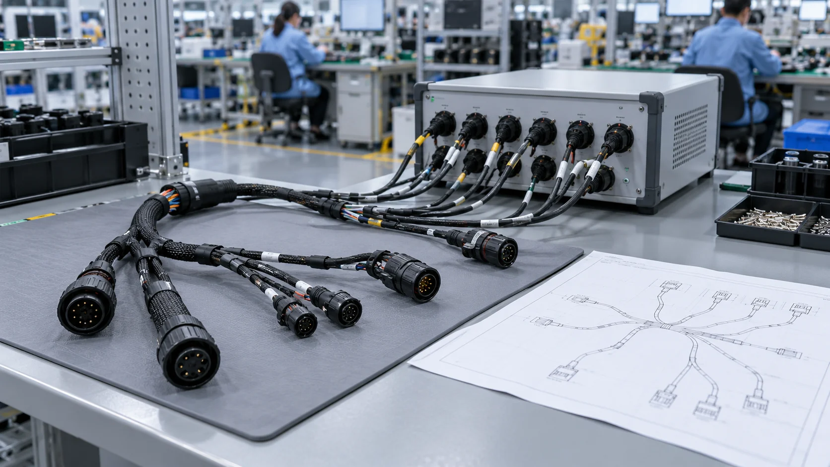
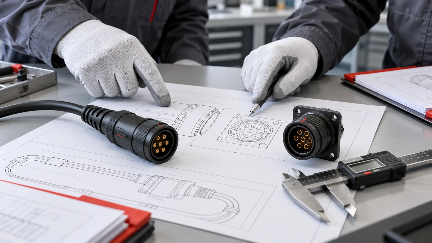
A 6 pin circular connector can mate correctly and still carry the wrong circuit. This OEM checklist separates contact numbering, drawing views, mechanical keying, and electrical mapping so engineers and buyers can approve a defined connector pair before releasing a cable assembly.
Start with the Exact Mating Pair
A 6 pin circular connector describes a contact count and a general shape. It does not define a universal interface. Two products can each contain six contacts while using different shell dimensions, insert patterns, coupling systems, key positions, and electrical ratings. Treat the cable plug and equipment receptacle as an approved pair with separate orderable part numbers.
Request both drawings before assigning wires. Record the series, complete suffix, contact gender, insert arrangement, mounting style, and drawing revision. Distinguish a connector sold with contacts from a housing that requires separately ordered contacts. An apparently missing position may be an intentionally unused cavity, a different insert, or an incomplete sample.
Compare the sample markings against the purchase order and drawing. A catalog photograph can represent a family rather than the exact variant. Resolve any discrepancy before the sample becomes a reference for assembly. JNICON's six-pin circular connector selection guide provides the broader application context; the checks below concentrate on interface identity and wiring release.
Read the Mating Face and Termination View Correctly
The viewing direction must be written beside every contact arrangement. Looking into the mating face means looking at the surface that meets the other connector. Looking at the termination side means looking toward the rear solder cups, crimp cavities, or wire-entry positions. Moving between these views can reverse the apparent left-to-right order.
Place the drawing's key reference in the stated orientation, then identify the actual cavity markings. Never decide that numbering runs clockwise merely because a photograph appears to show it. A male drawing and female drawing may use different perspectives. Copying numbers from one face onto the other can create a mirrored wiring error even when every wire passes a visual check.
Ask the supplier to annotate the sample photograph with the same view name and reference feature as the drawing. Keep that photograph beside the controlled work instruction. For right-angle versions, document the cable exit direction separately from the insert's numbering. Rotating a cable outlet for packaging does not authorize a different pin assignment.
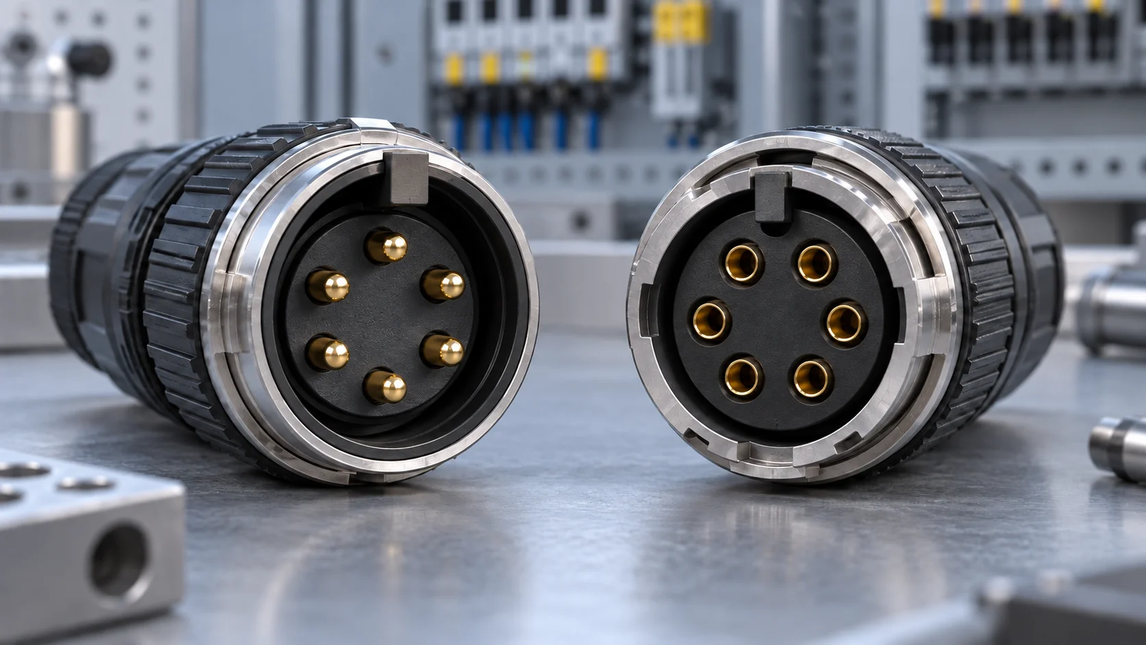
The illustration shows generic mating faces only. Its unnumbered contacts must never be used as a production pinout.
Separate Contact Gender from Shell and Mounting Style
When a buyer asks for a 6 pin circular connector male, confirm whether “male” refers to exposed pin contacts, the shell description, or a supplier's ordering convention. Use the manufacturer's explicit contact-gender terminology in the approved bill of materials. A panel-mounted component can contain pins or sockets, and a cable-mounted component can also contain either.
Record cable plug, inline receptacle, front-panel receptacle, or rear-panel receptacle as a separate field. Include the panel thickness range and retention hardware where relevant. A connector that mates electrically may still be impossible to install because its flange, mounting nut, or rear termination envelope conflicts with the enclosure.
Photograph the sample from the mating side and cable-entry side. Include one clear identifying feature without relying on color alone. Stores and maintenance teams should be able to match an approved replacement to its part number and drawing even when the original packaging is missing.
Use Keying to Control Mating Orientation
A 6 pin keyed circular connector uses a mechanical feature to constrain orientation. That feature may be a keyway, an asymmetric insert, or another model-specific geometry. Check that the two halves share the intended arrangement and that the coupling reaches its specified final position without force.
Mechanical keying does not establish circuit polarity. A correctly keyed pair can still have power and signal wires assigned to the wrong cavities. Two identical keyed interfaces on adjacent machine ports can also accept the wrong cable unless the system provides distinct coding or another approved prevention measure. Keep mechanical compatibility and electrical mapping as separate approval decisions.
Make a port-to-cable matrix for installations with repeated connectors. List each permitted combination and any prohibited combination that needs verification. Review wrong-port risk on de-energized samples using the manufacturer's permitted handling method. Do not force incompatible parts, remove keys, or file an insert to make it fit.
External labels help identification but can wear or become hidden. Where an incorrect connection creates a hazard, the equipment designer must determine the necessary protective measures and validation. A color band alone is not evidence that an interface is safe.
Do Not Treat Six-Pin DIN as an Interchangeability Claim
The phrase 6 pin circular DIN connector narrows the product search but still leaves questions about the applicable interface, contact arrangement, and exact variant. Determine the specific standard or manufacturer's series cited by the drawing. A generic seller description is insufficient for cross-mating approval.
TE Connectivity lists a six-position circular DIN product with keyed alignment and separate drawings and specifications. Harwin's six-position C90 product directs users to its component specification for complete pin numbering. These examples show why a contact count must be followed by product-specific documentation. They do not establish interchangeability with JNICON products or transfer another manufacturer's ratings.
Use the manufacturer's six-position DIN product documentation and C90 pin-numbering reference as examples of the evidence to request. For a replacement project, obtain written confirmation of the proposed mating pair and validate the complete assembly. Avoid comparing all DIN products with all sealed industrial products as if each group shared one rating.
Build a Six-Row Electrical Mapping Table
Create one controlled mapping table before terminating the first sample. Each physical contact needs a row even if the circuit leaves it unused. Use the manufacturer's contact identifier exactly as printed on the drawing; the numbers below describe rows in a checklist, not a universal pin assignment.
| Required field | What the approval record must contain |
|---|---|
| Contact identifier and view | Drawing cavity designation, mating or termination view, key reference |
| Circuit function | Actual net name, source, destination, and intended electrical role |
| Conductor identity | Wire label, color if used, cross-section, and cable reference |
| Opposite endpoint | Connector designation plus terminal or cavity identifier |
| Acceptance check | Expected connection and prohibited connections to verify |
| Release reference | Harness drawing revision, reviewer, sample, and test-program revision |
Do not assign supply, return, protective earth, or communications functions from wire color alone. Document a required protective connection explicitly under the applicable equipment design. Likewise, unused contacts must have a defined treatment. Leaving an unused wire loose inside a backshell creates a different risk from leaving an approved cavity unpopulated.
A crossed cable may be deliberate, such as connecting one endpoint's transmit function to another endpoint's receive function. Judge the assembly against its netlist rather than assuming that every cable is straight-through. Pair-specific tests belong to the actual protocol and cable construction.
Keep Power Ratings and Signal Requirements Separate
For a 6 pin circular power connector, confirm the rating of the selected contact configuration and assembly. Contact count does not determine current capacity. Review conductor size, termination method, simultaneous loading, ambient temperature, duty cycle, and the manufacturer's operating limits. A power-and-signal hybrid with six total contacts may contain differently sized contacts with different permissible duties.
The JNICON M16 2+4 and M40 2+4 families illustrate six-total-contact hybrid layouts. Their power and signal groups require their own approved assignments. They must not be represented as interchangeable six-equal-contact inserts. A different-contact-count product can be a redesign option, but it is not a drop-in replacement.
For communication circuits, check the interface specification, pairing, shielding, and end-to-end performance. A low-resistance continuity result cannot establish Ethernet, encoder, or other high-frequency performance. For mixed circuits, use the separate hybrid connector EMI review checklist to define the operating test conditions. If heat is the concern, review the connector temperature-rise checklist against the exact model rather than borrowing a catalog maximum.
Verify the Unpowered Assembly Against the Netlist
Complete visual and mechanical identification before electrical verification. The assembly must be isolated from power sources and connected electronics under the equipment's approved safety procedure. Use suitable fixtures and an approved test method. This article does not supply universal insulation-test voltages, acceptance resistance limits, or an energized troubleshooting procedure.
Check each intended connection from its physical cavity to the opposite endpoint. Then check the relevant unintended paths. Testing only the six expected continuities can miss a bridge between adjacent circuits. Include any required shell, drain, shield, or protective connections as separately defined nets, and avoid counting an intentional common connection as a fault.
Validate the fixture as well as the cable. An incorrectly numbered breakout fixture can make a mirrored harness appear correct. Have an independent review compare the fixture labels and test program against the approved mating-face drawings. Use a controlled verification sample or approved fault-insertion method to demonstrate that the test detects the mistakes it is meant to reject.
Record results by sample identity and drawing revision. Where intermittent opens are relevant, use the approved movement conditions and event criteria from the cable assembly pinout and intermittent-fault test guide. Passing continuity establishes only the connections covered by that test. Environmental, thermal, and communication evidence remain separate.
Check the Installed Interface and Maintenance Access
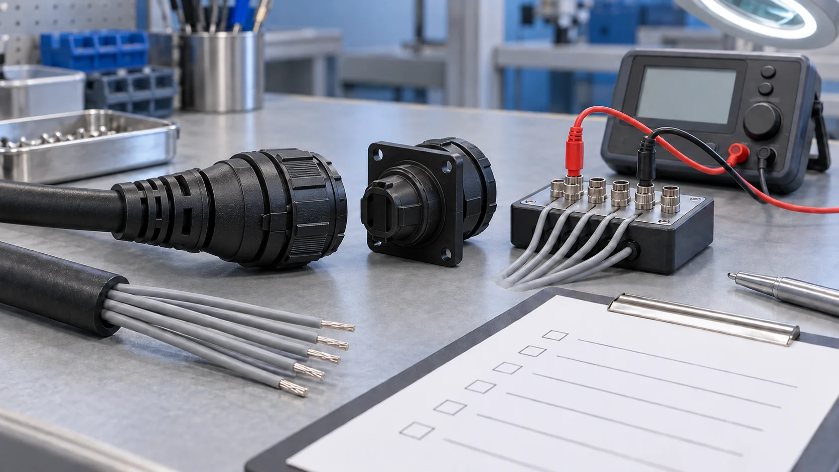
A correct bench assembly can become difficult to identify after installation. Review the connector in its actual panel position with the intended cable route, adjacent ports, cover, and service access. Confirm that the key reference and locking indication remain observable using the specified installation method.
Check that cable bending or strain does not rotate the termination or load the contact system. A right-angle exit may improve packaging while making an adjacent cable harder to disconnect. Verify the required service clearance before the panel cutout is released. Avoid letting a removable cable carry the weight of another assembly.
Sealing must be checked for the exact mated or capped state, cable diameter, gland, and assembly instructions. An IP claim does not identify the pinout or prove that an unmated connector remains protected. Keep spare caps and replacement cables identified by approved part number. Maintenance instructions should name the replacement configuration and the checks required after replacement, rather than showing only a generic six-pin photograph.
Release a Drawing Pack That Production Can Use
A production pack should let a second assembler reproduce the approved sample without interpreting an email thread. Include the two mating-half drawings, contact arrangement views, harness netlist, cable specification, termination instructions, identification rules, and final inspection criteria. Give each document a revision and an owner.
Separate reference images from acceptance requirements. A picture of an approved sample is useful for orientation, but hidden cavity numbers or perspective distortion can make it unsuitable as the sole work instruction. If a drawing and photograph disagree, stop and resolve the discrepancy through document control.
Keep test-program revision linked to harness revision. A supplier's change in insert numbering, cable color, or contact tooling may require an update even if the external shell looks unchanged. Define which changes need approval before production resumes. Retain the approved sample with its identity and condition recorded; wear or rework can make an old sample unsuitable as a master.
The OEM connector RFQ and sample approval checklist covers supplier responsibilities and sample-release evidence. Use it alongside the interface pack when requesting a new design or an alternative supplier.
Define the approval boundary for replacement parts as well. A change in contact finish, seal, or termination tool can affect evidence beyond the wiring table. Purchasing should retain the approved manufacturer reference and revision on the order. If a supplier proposes a substitute, route it through the named engineering reviewer before the substitute enters the production stock location.
Use a Focused Fault Review Before Reordering
When a replacement does not work, compare the identifiers before replacing more parts. A plug that will not mate may have a different key, insert, or locking system. A pair that locks but fails electrically may have a mirrored drawing interpretation, an incorrect endpoint mapping, or a termination fault.
Work from the last approved configuration. Compare the affected assembly's serial or batch identity, part-number suffixes, drawing revisions, and test-program version. Preserve the suspect assembly for inspection. Swapping multiple cables and receptacles at once makes it harder to identify which change corrected the fault.
- If continuity is mirrored, review mating-face versus termination-side interpretation and fixture numbering.
- If the expected path is correct but another circuit is connected, investigate unwanted bridges and common-net assumptions.
- If a cable fits another port, review the system's coding and wrong-port prevention decision.
- If failures depend on movement, preserve the movement conditions for a separate intermittent-fault review.
Record the confirmed cause and the approved corrective action. A replacement purchase should cite the corrected specification rather than repeat an ambiguous “circular 6 pin connector” description.
Send JNICON an Interface Review Request
For a new circular 6 pin connector request, send the exact mating-half references or clear photographs, the equipment-side drawing, and the six-contact function table. State the cable construction and installation conditions. If the project is a redesign, identify which dimensions and electrical interfaces must remain unchanged.
Ask JNICON to confirm the proposed series, contact layout, mating parts, available termination approach, and the documents needed for sample evaluation. Request clarification where a rating or drawing is incomplete. Treat the proposal as a candidate until the equipment team approves its electrical mapping and application validation.
For a replacement sourced from another brand, provide that brand's complete part numbers and drawings. Do not authorize manufacture based only on a nominal shell size or contact count. A proposal that needs a new receptacle, new panel cutout, or changed wiring should be identified as a redesign so purchasing can compare the full scope.
A useful approval record names the accepted configuration, outstanding tests, responsible reviewer, and release condition. It gives production a specific next action while keeping unresolved interface questions visible.
Related Products for Interface Reviews
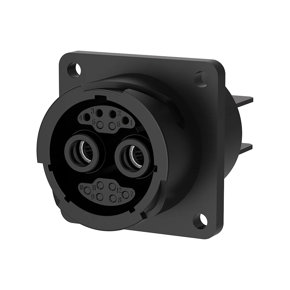
M40 2+4 Pin Hybrid Waterproof Connector for Power and Signal
120A+10A hybrid bayonet lock waterproof connector combining power and signal in one compact design.
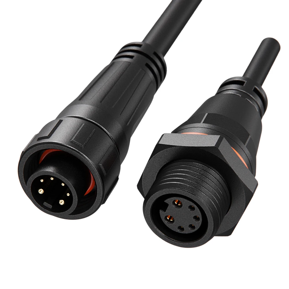
M16 2+4 Pin Hybrid Waterproof Connector 10A+5A Screw Locking IP68 for Power & Signal
10A+5A hybrid screw-locking waterproof connector combining power and signal in one M16 housing, field installable or molded with cable.
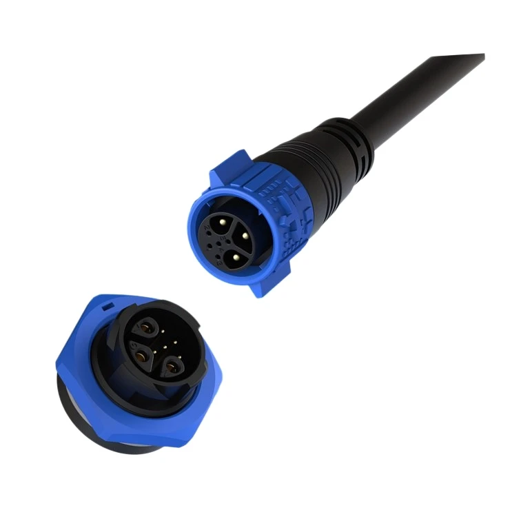
M19 3+5 Pin Hybrid Waterproof Connector 15A+5A Push Locking IP67 for Power & Signal
15A+5A hybrid push-locking waterproof connector combining power and multi-signal in one M19 housing for industrial control systems.
Related Industrial Solutions

Industrial Automation
Power, signal, and data connectivity for factory machines, robotic cells, sensors, and control cabinets. JNICON can review circular connectors and cable assemblies against motion, sealing, shielding, and maintenance requirements before prototype approval.
Explore Solutions
Marine & Offshore
Sealed power, signal and cable interfaces for marine equipment and offshore installations. Review salt exposure, condensation, vibration, cleaning and service conditions with JNICON. A stated IP68 rating does not by itself establish continuous subsea, pressure-depth or marine-class approval.
Explore Solutions
New Energy & Energy Storage
Connector and cable assembly options for battery racks, BMS interfaces, power conversion equipment and energy-storage cabinets. JNICON supports configuration review based on current, voltage, thermal conditions, polarity, service access and environmental exposure.
Explore SolutionsFAQ: Six-Pin Pinout and Keying
Conclusion: Approve the Pair and Its Wiring Together
Approve a six-pin interface with a matched pair of part numbers, clearly named drawing views, an explicit contact-function table, and verified test coverage. Keep keying, circuit mapping, sealing, and operating performance as separate requirements. A successful check in one area does not close the others.
Send JNICON your drawings, cable details, and operating requirements to request a six-pin connector interface review and OEM quotation. Confirm the proposed configuration and sample acceptance criteria before placing a production order.